CRT 48 Operation - Wacker Neuson
CRT 48 Operation - Wacker Neuson
CRT 48 Operation - Wacker Neuson
Create successful ePaper yourself
Turn your PDF publications into a flip-book with our unique Google optimized e-Paper software.
OPERATOR’S MANUAL<br />
0 1 6 3 2 0 4 E N<br />
0163204en 002<br />
1108<br />
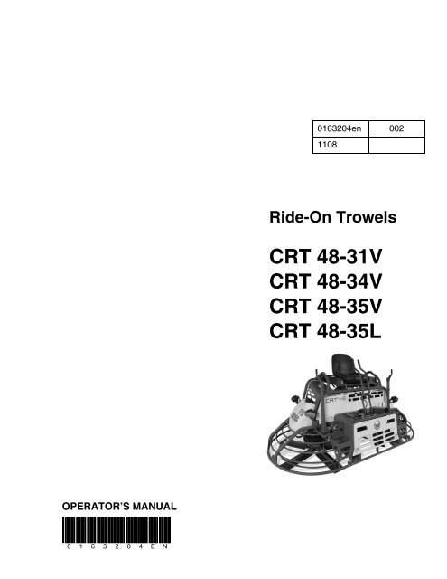
Ride-On Trowels<br />
<strong>CRT</strong> <strong>48</strong>-31V<br />
<strong>CRT</strong> <strong>48</strong>-34V<br />
<strong>CRT</strong> <strong>48</strong>-35V<br />
<strong>CRT</strong> <strong>48</strong>-35L
Foreword<br />
WARNING<br />
CALIFORNIA<br />
Proposition 65 Warning:<br />
Engine exhaust, some of its constituents, and certain vehicle<br />
components, contain or emit chemicals known to the State of<br />
California to cause cancer and birth defects or other reproductive<br />
harm.<br />
This manual provides information and procedures to safely operate<br />
and maintain this <strong>Wacker</strong> <strong>Neuson</strong> model. For your own safety and<br />
protection from injury, carefully read, understand and observe the<br />
safety instructions described in this manual.<br />
Keep this manual or a copy of it with the machine. If you lose this<br />
manual or need an additional copy, please contact <strong>Wacker</strong> <strong>Neuson</strong><br />
Corporation. This machine is built with user safety in mind; however,<br />
it can present hazards if improperly operated and serviced. Follow<br />
operating instructions carefully! If you have questions about operating<br />
or servicing this equipment, please contact <strong>Wacker</strong> <strong>Neuson</strong><br />
Corporation.<br />
The information contained in this manual was based on machines in<br />
production at the time of publication. <strong>Wacker</strong> <strong>Neuson</strong> Corporation<br />
reserves the right to change any portion of this information without<br />
notice.<br />
All rights, especially copying and distribution rights, are reserved.<br />
Copyright 2008 by <strong>Wacker</strong> <strong>Neuson</strong> Corporation.<br />
No part of this publication may be reproduced in any form or by any<br />
means, electronic or mechanical, including photocopying, without<br />
express written permission from <strong>Wacker</strong> <strong>Neuson</strong> Corporation.<br />
Any type of reproduction or distribution not authorized by <strong>Wacker</strong><br />
<strong>Neuson</strong> Corporation represents an infringement of valid copyrights<br />
and will be prosecuted. We expressly reserve the right to make<br />
technical modifications, even without due notice, which aim at<br />
improving our machines or their safety standards.<br />
wc_tx000001gb.fm 3
wc_tx000001gb.fm 4
<strong>CRT</strong> <strong>48</strong> Table of Contents<br />
Foreword 3<br />
1. Safety Information 7<br />
1.1 Laws Pertaining to Spark Arresters ...................................................... 7<br />
1.2 Operating Safety .................................................................................. 8<br />
1.3 Operator Safety while using Internal Combustion Engines .................. 9<br />
1.4 Service Safety .................................................................................... 10<br />
1.5 Transport Safety ................................................................................. 10<br />
1.6 Label Locations .................................................................................. 11<br />
1.7 Safety and Operating Labels .............................................................. 13<br />
2. <strong>Operation</strong> 19<br />
2.1 Description ......................................................................................... 19<br />
2.2 Features and Controls ........................................................................ 20<br />
2.3 New Machines .................................................................................... 22<br />
2.4 Before Starting ................................................................................... 23<br />
2.5 Starting-Vanguard .............................................................................. 23<br />
2.6 Starting-Lombardini ............................................................................ 23<br />
2.7 Stopping ............................................................................................. 24<br />
2.8 <strong>Operation</strong> ............................................................................................ 24<br />
2.9 Steering .............................................................................................. 25<br />
2.10 Pitch Adjustment ................................................................................ 26<br />
3. Maintenance 27<br />
3.1 Periodic Maintenance Schedule ......................................................... 27<br />
3.2 Trowel Gearboxes .............................................................................. 28<br />
3.3 Control Linkage Lubrication ................................................................ 30<br />
3.4 Control Arm Adjustment (Forward or Backward) ................................ 30<br />
3.5 Steering Assist System ...................................................................... 30<br />
3.6 Right-hand Control Arm Adjustment (Right or Left) ............................ 31<br />
3.7 Blade Arm Adjustment ........................................................................ 32<br />
3.8 Mounting Float Pans .......................................................................... 32<br />
3.9 Transporting Trowels .......................................................................... 33<br />
3.10 Drive Belt ............................................................................................ 34<br />
3.11 Battery Jump Start Procedure ............................................................ 35<br />
wc_bo0163204en_002TOC.fm 5
Table of Contents <strong>CRT</strong> <strong>48</strong><br />
3.12 Spark Plug-Vanguard ..........................................................................36<br />
3.13 Air Cleaner ..........................................................................................37<br />
3.14 Engine Oil and Filter–Vanguard Engines ............................................38<br />
3.15 Engine Oil and Filter–Lombardini Diesel .............................................40<br />
3.16 Troubleshooting ...................................................................................41<br />
4. Technical Data 43<br />
4.1 Engine .................................................................................................43<br />
4.2 Trowel ..................................................................................................44<br />
4.3 Sound and Vibration Specifications .....................................................45<br />
wc_bo0163204en_002TOC.fm 6
<strong>CRT</strong> <strong>48</strong> Safety Information<br />
1. Safety Information<br />
DANGER<br />
WARNING<br />
CAUTION<br />
This manual contains DANGER, WARNING, CAUTION, NOTICE and<br />
NOTE callouts which must be followed to reduce the possibility of<br />
personal injury, damage to the equipment, or improper service.<br />
This is the safety alert symbol. It is used to alert you to potential<br />
personal injury hazards. Obey all safety messages that follow this<br />
symbol to avoid possible injury or death.<br />
DANGER indicates a hazardous situation which, if not avoided, will<br />
result in death or serious injury.<br />
WARNING indicates a hazardous situation which, if not avoided, could<br />
result in death or serious injury.<br />
CAUTION indicates a hazardous situation which, if not avoided, could<br />
result in minor or moderate injury.<br />
NOTICE: Used without the safety alert symbol, NOTICE indicates a<br />
situation which, if not avoided, could result in property damage.<br />
Note: Contains additional information important to a procedure.<br />
1.1 Laws Pertaining to Spark Arresters<br />
Notice: State Health Safety Codes and Public Resources Codes<br />
specify that in certain locations spark arresters be used on internal<br />
combustion engines that use hydrocarbon fuels. A spark arrester is a<br />
device designed to prevent accidental discharge of sparks or flames<br />
from the engine exhaust. Spark arresters are qualified and rated by<br />
the United States Forest Service for this purpose.<br />
In order to comply with local laws regarding spark arresters, consult<br />
the engine distributor or the local Health and Safety Administrator.<br />
wc_si000188gb.fm 7
Safety Information <strong>CRT</strong> <strong>48</strong><br />
1.2 Operating Safety<br />
Familiarity and proper training are required for the safe operation of the<br />
machine. Machines operated improperly or by untrained personnel can<br />
be dangerous. Read the operating instructions contained in both this<br />
manual and the engine manual and familiarize yourself with the location<br />
and proper use of all controls. Inexperienced operators should receive<br />
instruction from someone familiar with the machine before being allowed<br />
to operate it.<br />
1.2.1 NEVER operate this machine in applications for which it is not intended.<br />
1.2.2 Do not allow anyone to operate this equipment without proper training.<br />
People operating this equipment must be familiar with the risks and<br />
hazards associated with it.<br />
1.2.3 Do not touch the engine or muffler while the engine is on or immediately<br />
after it has been turned off. These areas get hot and may cause burns.<br />
1.2.4 Do not use accessories or attachments that are not recommended by<br />
<strong>Wacker</strong> <strong>Neuson</strong>. Damage to equipment and injury to the user may<br />
result.<br />
1.2.5 NEVER operate the machine with the beltguard missing. Exposed drive<br />
belt and pulleys create potentially dangerous hazards that can cause<br />
serious injuries.<br />
1.2.6 NEVER leave the machine running unattended.<br />
1.2.7 Do not run the machine indoors or in an enclosed area such as a deep<br />
trench unless adequate ventilation, through such items as exhaust fans<br />
or hoses, is provided. Engine exhaust contains carbon monoxide. This is<br />
a poison you cannot see or smell. Exposure to carbon monoxide can<br />
cause loss of consciousness and CAN KILL YOU IN MINUTES.<br />
1.2.8 ALWAYS remain aware of moving parts and keep hands, feet, and loose<br />
clothing away from the moving parts of the machine.<br />
1.2.9 ALWAYS wear protective clothing appropriate to the job site when<br />
operating the machine.<br />
1.2.10 Read, understand, and follow procedures in the Operator’s Manual<br />
before attempting to operate the machine.<br />
1.2.11 Be sure operator is familiar with proper safety precautions and operation<br />
techniques before using machine.<br />
1.2.12 Close fuel valve on engines equipped with one when machine is not<br />
being operated.<br />
1.2.13 Store the machine properly when it is not being used. The machine<br />
should be stored in a clean, dry location out of the reach of children.<br />
1.2.14 ALWAYS operate the machine with all safety devices and guards in<br />
place and in working order.<br />
WARNING<br />
8
<strong>CRT</strong> <strong>48</strong> Safety Information<br />
1.3 Operator Safety while using Internal Combustion Engines<br />
DANGER<br />
Internal combustion engines present special hazards during operation<br />
and fueling. Read and follow the warning instructions in the engine<br />
owner’s manual and the safety guidelines below. Failure to follow the<br />
warnings and safety standards could result in severe injury or death.<br />
1.3.1 Do not run the machine indoors or in an enclosed area such as a deep<br />
trench unless adequate ventilation, through such items as exhaust fans<br />
or hoses, is provided. Engine exhaust contains carbon monoxide. This is<br />
a poison you cannot see or smell. Exposure to carbon monoxide can<br />
cause loss of consciousness and CAN KILL YOU IN MINUTES.<br />
1.3.2 Do not smoke while operating the machine.<br />
1.3.3 Do not smoke when refueling the engine.<br />
1.3.4 Do not refuel a hot or running engine.<br />
1.3.5 Do not refuel the engine near an open flame.<br />
1.3.6 Do not spill fuel when refueling the engine.<br />
1.3.7 Do not run the engine near open flames.<br />
1.3.8 Refill the fuel tank in a well-ventilated area.<br />
1.3.9 Replace the fuel tank cap after refueling.<br />
1.3.10 Keep the area around the muffler free of debris such as leaves, paper,<br />
cartons, etc. A hot muffler could ignite the debris and start a fire.<br />
wc_si000188gb.fm 9
Safety Information <strong>CRT</strong> <strong>48</strong><br />
1.4 Service Safety<br />
WARNING<br />
A poorly maintained machine can become a safety hazard! In order<br />
for the machine to operate safely and properly over a long period of<br />
time, periodic maintenance and occasional repairs are necessary.<br />
1.4.1 Do not attempt to clean or service the machine while it is running.<br />
Rotating parts can cause severe injury.<br />
1.4.2 Do not crank a flooded engine with the spark plug removed on<br />
gasoline-powered engines. Fuel trapped in the cylinder will squirt out<br />
the spark plug opening.<br />
1.4.3 Do not test for spark on gasoline-powered engines if the engine is<br />
flooded or the smell of gasoline is present. A stray spark could ignite<br />
the fumes.<br />
1.4.4 Do not use gasoline or other types of fuels or flammable solvents to<br />
clean parts, especially in enclosed areas. Fumes from fuels and<br />
solvents can become explosive.<br />
1.4.5 ALWAYS turn engine off and remove key from machine before<br />
performing maintenance or making repairs.<br />
1.4.6 ALWAYS handle blades carefully. The blades can develop sharp<br />
edges which can cause serious cuts.<br />
1.4.7 Keep the area around the muffler free of debris such as leaves, paper,<br />
cartons, etc. A hot muffler could ignite the debris and start a fire.<br />
1.4.8 Replace worn or damaged components with spare parts designed and<br />
recommended by <strong>Wacker</strong> <strong>Neuson</strong> Corporation.<br />
1.4.9 Disconnect the spark plug on machines equipped with gasoline<br />
engines, before servicing, to avoid accidental start-up.<br />
1.4.10 ALWAYS switch off the power supply at the battery disconnect before<br />
adjusting or maintaining the electrical equipment.<br />
1.4.11 Keep the machine clean and labels legible. Replace all missing and<br />
hard-to-read labels. Labels provide important operating instructions<br />
and warn of dangers and hazards.<br />
1.5 Transport Safety<br />
1.5.1 Always engage the steering handle lock before lifting the machine.<br />
WARNING<br />
DO NOT lift the trowel by the guard rings or any part of the trowel other<br />
than the lifting fixture, as the component may fail, causing the trowel to<br />
fall, possibly injuring bystanders.<br />
10
<strong>CRT</strong> <strong>48</strong> Safety Information<br />
T<br />
S<br />
R<br />
F<br />
1.6 Label Locations<br />
D<br />
wc_si000188gb.fm 11<br />
M<br />
Z<br />
I<br />
Q<br />
BB<br />
N<br />
Z<br />
L CC<br />
BB<br />
M<br />
E<br />
U<br />
I<br />
L<br />
Q<br />
wc_gr003770<br />
C
Safety Information <strong>CRT</strong> <strong>48</strong><br />
W<br />
H<br />
V<br />
M<br />
J<br />
O<br />
BB<br />
12<br />
BB M<br />
W<br />
G<br />
H<br />
AA<br />
K<br />
wc_gr003771<br />
A/B
<strong>CRT</strong> <strong>48</strong> Safety Information<br />
1.7 Safety and Operating Labels<br />
<strong>Wacker</strong> <strong>Neuson</strong> machines use international pictorial labels where<br />
needed. These labels are described below:<br />
Ref. Label Meaning<br />
A DANGER!<br />
No sparks, flames, or burning objects near the<br />
machine. Shut off the engine before refueling.<br />
Use only clean, filtered unleaded gasoline.<br />
Engines emit carbon monoxide; operate only<br />
in well-ventilated area.<br />
B DANGER!<br />
No sparks, flames, or burning objects near the<br />
machine. Shut off the engine before refueling.<br />
Use only clean, filtered diesel fuel. Engines<br />
emit carbon monoxide; operate only in wellventilated<br />
area.<br />
C Water tank fill. Use only clean water or waterbased<br />
retardants.<br />
D WARNING!<br />
Always wear hearing and eye protection when<br />
operating this machine.<br />
E Steering control. Refer to section Steering.<br />
wc_si000188gb.fm 13
Safety Information <strong>CRT</strong> <strong>48</strong><br />
Ref. Label Meaning<br />
F WARNING!<br />
Read and understand the supplied Operator’s<br />
Manual before operating the machine. Failure<br />
to do so increases the risk of injury to yourself<br />
or others.<br />
G WARNING!<br />
Hot surface!<br />
H WARNING!<br />
Cutting hazard. Always replace blade guard!<br />
J WARNING!<br />
Pressurized contents. Do not open when hot!<br />
K WARNING!<br />
Hand injury if caught in moving belt.<br />
Always replace beltguard.<br />
L CAUTION!<br />
Lifting point.<br />
M Tie-down point.<br />
14
<strong>CRT</strong> <strong>48</strong> Safety Information<br />
Ref. Label Meaning<br />
N Key switch, engine start:<br />
Off<br />
On<br />
Start<br />
O Operator’s Manual must be stored on<br />
machine. Replacement Operator’s Manual can<br />
be ordered through your local <strong>Wacker</strong> <strong>Neuson</strong><br />
distributor.<br />
P WARNING!<br />
4 A � � L A F = � B H � � J H � M A � > A B � H A � E B J E � C � = ? D E � A<br />
� L A H D A = @ �<br />
2 = � I ? = � B = � � = � @ ? = K I A @ A = J D � H I A H E � K I E � � K H O E B<br />
= F A H I � � E I D E J �<br />
/ � A E J I ? D A E > A L � � * A J � � C � � J J A H A � J B A H � A � > A L � H<br />
@ = I / A H � J K > A H � � F B D � D A C A D � > A � M E H @ �<br />
/ � A E J I ? D A E > A � = � � B = � � A � K � @ I ? D M A H A 8 A H � A J � K � C<br />
� @ A H 6 � @ L A H K H I = ? D A � M A � � 2 A H I � � = � C A J H � B B A � M E H @ �<br />
3 K E J A A � @ E I ? � @ A B � � J = ? E � � = � J A I @ A � A L = � J = H � =<br />
� � G K E � = = � E I = @ � H = @ A D � H � E C � � �<br />
� � I @ E I ? � I F � @ H � = � ? = A H O � = J = H � � = I J E � = H<br />
I A H E = � A � J A = K � = F A H I � � = G K A I A A � ? K A � J H A ? A H ? = �<br />
) L = � J @ A � A L A H � \ = F F = H A E � = K � @ A I I K I @ A L � J H A J � J A �<br />
� J A H � A @ E I G K A @ A J = � � ? D = C A @ A � = J H K A � � A �<br />
� A @ E I G K A @ A J = � � ? D = C A F A K J J � � > A H A J A � J H = � � A H<br />
@ A C H = L A I > � A I I K H A I � K � � � A � = � � H J �<br />
wc_si000188gb.fm 15<br />
& $ & &<br />
Remove pan from trowel before lifting machine<br />
overhead. Pans can fall and cause death or<br />
serious injury if a person is hit. (Located on top<br />
side of float pan.)<br />
Q Blade pitch control. Turn both controls inward<br />
to increase blade pitch. Refer to section Pitch<br />
Adjustment.<br />
R CAUTION!<br />
Engine oil pressure is low! Stop the engine<br />
and check the oil level.<br />
S CAUTION!<br />
Low voltage! Stop the engine and check the<br />
charging system.
Safety Information <strong>CRT</strong> <strong>48</strong><br />
Ref. Label Meaning<br />
T CAUTION!<br />
Coolant temperature is too high. Stop the<br />
engine and check the coolant level.<br />
U CAUTION!<br />
Glow plugs activated. Do not start engine until<br />
light turns off.<br />
V WARNING!<br />
Pinching hazard. Rotating machinery.<br />
W Use only Glygoyle 460 gear oil in gearbox.<br />
WACKER NEUSON<br />
X A nameplate listing the model number, item<br />
number, revision number, and serial number is<br />
attached to each unit. Please record the<br />
information found on this plate so it will be<br />
available should the nameplate become lost or<br />
damaged. When ordering parts or requesting<br />
service information, you will always be asked<br />
to specify the model number, item number,<br />
revision number, and serial number of the unit.<br />
Y This machine may be covered by one or more<br />
patents.<br />
16
<strong>CRT</strong> <strong>48</strong> Safety Information<br />
Ref. Label Meaning<br />
Z Steering system components are under load.<br />
See Steering section or a trained service<br />
technician for adjustments.<br />
AA Engage manual steering handle lock before<br />
lifting.<br />
BB Fork lift pockets.<br />
CC Low sulfur fuel or ultra low sulfur fuel only.<br />
wc_si000188gb.fm 17
Safety Information <strong>CRT</strong> <strong>48</strong><br />
Notes<br />
18
<strong>CRT</strong> <strong>48</strong> <strong>Operation</strong><br />
2. <strong>Operation</strong><br />
2.1 Description<br />
The Ride-On Trowel is a modern, high production machine. Finishing<br />
rate will vary depending on operator skill and job conditions. The<br />
heavy-duty gearboxes are designed to provide exceptional<br />
performance, low maintenance, and trouble-free use in most<br />
conditions. The variable speed drive is designed to provide higher<br />
torque, to optimize performance with the use of pans. The machine<br />
can be used with either two pans or ten finishing blades.<br />
wc_tx000641gb.fm 19
<strong>Operation</strong> <strong>CRT</strong> <strong>48</strong><br />
2.2 Features and Controls<br />
wc_tx000641gb.fm 20
<strong>CRT</strong> <strong>48</strong> <strong>Operation</strong><br />
Control locations and functions:<br />
Ref. Description Ref. Description<br />
a Right pitch control l Engine choke control (if equipped)<br />
b Fuel tank m Work light switch<br />
c Control arms n Glow plug indicator light (if<br />
equipped)<br />
d Operator’s seat with “operator<br />
presence” switch<br />
o Engine keyswitch<br />
e Left pitch control p Hour meter<br />
f Rear work light (one each side) q Water spray control<br />
g Water tank r Oil pressure indicator light<br />
h Work light (one each side) s Alternator charging indicator light<br />
k Foot pedal (throttle control) t Coolant temperature indicator light<br />
The Ride-On Trowel features a seat with an integrated “operator<br />
presence” system, which works in conjunction with a throttle mounted<br />
switch. This system allows the engine to remain running (idling) with<br />
no operator seated in the seat, as long as the throttle is not depressed.<br />
This system meets all safety requirements and eliminates the need for<br />
a foot-operated “kill switch”.<br />
To familiarize a new operator with the Ride-On Trowel the following<br />
steps should be taken:<br />
2.2.1 With the operator in the seat, show him or her the functions of the<br />
control arms (c) and how to start the machine.<br />
2.2.2 Have the operator practice steering the trowel. A hard concrete slab<br />
slightly wetted with water is an ideal place for an operator to practice<br />
with the machine. For this practice, pitch the blades up approximately<br />
6,35 mm (¼") on the leading edge. Start by making the machine hover<br />
in one spot, and then practice driving the machine in a straight line and<br />
making 180° turns. The best control is achieved at full rpm.<br />
wc_tx000641gb.fm 21
<strong>Operation</strong> <strong>CRT</strong> <strong>48</strong><br />
2.3 New Machines<br />
See Graphic: wc_gr001252<br />
2.3.1 To break in the gearboxes, run the engine at 50% of full throttle for the<br />
first 2–4 hours. This will prevent premature wear and extend gear life.<br />
NOTICE: Running the engine at full throttle during the break-in period<br />
could result in premature gear failure.<br />
2.3.2 Verify that the horizontal blade pitch links are properly assembled.<br />
When seated on the machine, the right rotor should have an “R”<br />
designation located towards the upper portion of the pitch link and the<br />
left rotor should have an “L”.<br />
wc_tx000641gb.fm 22
<strong>CRT</strong> <strong>48</strong> <strong>Operation</strong><br />
2.4 Before Starting<br />
2.5 Starting-Vanguard<br />
Before starting the trowel, check the following:<br />
• fuel level<br />
• oil level in the engine<br />
• condition of the air filter<br />
• condition of trowel arms and blades<br />
Grease the trowel arms daily.<br />
Before starting the operator must know the location and function of all<br />
controls.<br />
2.5.1 Turn and hold engine keyswitch until the engine starts.<br />
Note: If the engine is cold, pull out the choke control knob fully.<br />
NOTICE: Cranking the engine for more than 5 seconds can cause<br />
starter damage. If the engine fails to start, release the keyswitch and<br />
wait 10 seconds before operating the starter again.<br />
2.5.2 Allow the engine to warm up before operating the trowel.<br />
2.6 Starting-Lombardini<br />
Before starting the operator must know the location and function of all<br />
controls.<br />
2.6.1 Turn the engine keyswitch to the run position.<br />
2.6.2 When the glow plug indicator light turns off, turn keyswitch to start<br />
position and hold until the engine starts.<br />
NOTICE: Cranking the engine for more than 5 seconds can cause<br />
starter damage. If the engine fails to start, release the keyswitch and<br />
wait 10 seconds before operating the starter again.<br />
2.6.3 Allow the engine to warm up before operating the trowel.<br />
wc_tx000641gb.fm 23
<strong>Operation</strong> <strong>CRT</strong> <strong>48</strong><br />
2.7 Stopping<br />
2.8 <strong>Operation</strong><br />
To stop trowel movement, return control levers to their neutral position<br />
and release pressure on the throttle foot pedal.<br />
To stop the engine, turn the keyswitch to “O” (off).<br />
To utilize your <strong>Wacker</strong> <strong>Neuson</strong> Ride-On Trowel to its fullest capacity,<br />
the machine should be driven in the direction that the operator is<br />
facing. This will finish the widest possible area, while giving the<br />
operator an excellent view of the slab surface about to be troweled.<br />
When the machine reaches the end of the slab, make a 180° U-turn,<br />
and repeat the straight line of direction to the other end of the slab.<br />
Note: During the break-in period, run the engine at 50% of full throttle.<br />
Refer to Section New Machines.<br />
NOTICE: DO NOT use excessive pressure on the control levers.<br />
Excessive pressure does not increase the reaction time of the machine<br />
and can damage the steering controls.<br />
NOTICE: Attempting to use the trowel too early in the curing stage of<br />
the concrete may result in an undesirable finish. Only experienced<br />
concrete finishers should operate the trowel.<br />
wc_tx000641gb.fm 24
<strong>CRT</strong> <strong>48</strong> <strong>Operation</strong><br />
2.9 Steering<br />
See Graphic: wc_gr000689<br />
Refer to the illustration for the necessary hand motions to move the<br />
trowel in the desired direction, described below.<br />
1 - forward<br />
2 - reverse<br />
3 - rotate clockwise<br />
4 - rotate counter-clockwise<br />
5 - left sideways<br />
6 - right sideways<br />
! "<br />
# $<br />
wc_tx000641gb.fm 25<br />
M ? � C H $ & '
<strong>Operation</strong> <strong>CRT</strong> <strong>48</strong><br />
b<br />
2.10 Pitch Adjustment<br />
a<br />
wc_gr000147<br />
See Graphic: wc_gr000147<br />
When changing or setting the pitch (angle) of the trowel blades, slow<br />
the machine, set the desired pitch on the left side of the machine, then<br />
adjust the right side to match.<br />
To increase the pitch, turn the pitch control inward (a). Use the pitch<br />
indicator (b) to adjust pitch equally on both right and left trowel blades.<br />
25° 4<br />
3<br />
2<br />
0° 1<br />
5-10º<br />
wc_tx000641gb.fm 26<br />
15º<br />
20-25º<br />
Working Conditions of<br />
Concrete<br />
Suggested Working<br />
Pitch<br />
1. Wet surface working stage Flat (No Pitch)<br />
2. Wet to plastic working<br />
stage<br />
Slight Pitch<br />
3. Semi-hard working stage Additional Pitch<br />
4. Hard finishing stage<br />
(burnishing)<br />
Maximum Pitch
<strong>CRT</strong> <strong>48</strong> Maintenance<br />
3. Maintenance<br />
3.1 Periodic Maintenance Schedule<br />
The chart below lists basic trowel and engine maintenance. Refer to engine manufacturer’s<br />
operator’s manual for additional information on engine maintenance. A copy of the engine<br />
operator’s manual was supplied with the machine when it was shipped. To service the engine, tilt<br />
the seat forward.<br />
Grease trowel arms. �<br />
Check fuel level. �<br />
Check engine oil level. �<br />
wc_tx000642gb.fm 27<br />
Daily Every<br />
20<br />
hrs.<br />
Every<br />
50<br />
hrs.<br />
Every<br />
100<br />
hrs.<br />
Every<br />
200<br />
hrs.<br />
Inspect air filter. Replace as needed. � � �<br />
Check external hardware. �<br />
Pressure wash all surfaces until free of<br />
concrete.<br />
Check coolant level. �<br />
Check oil level in gearboxes. �<br />
Grease gearbox input shaft fitting �<br />
Grease control linkage. 1 �<br />
Check drive belt for wear. �<br />
Change engine oil. 2, 3 � �<br />
Check fuel filter. �<br />
Clean and check spark plug. �<br />
Replace oil filter. 2 � �<br />
Check fan belt. �<br />
Replace spark plug. �<br />
Replace fuel filter. �<br />
Replace oil in gearboxes. �<br />
Change coolant. �<br />
1 Manual steering models only. 2 Perform initially after first 50 hours of operation.<br />
3 250 hours for diesel.<br />
�<br />
Every<br />
300<br />
hrs.
Maintenance <strong>CRT</strong> <strong>48</strong><br />
3.2 Trowel Gearboxes<br />
See Graphic: wc_gr003781<br />
Check the gearboxes for the correct oil level after every 20 hours of<br />
operation. Change the gearbox oil every 300 hours.<br />
To check the oil level:<br />
Each <strong>CRT</strong> gearbox is equipped with two oil fill plugs. Remove one<br />
gearbox oil fill plug (b). If the level is below the threads of the oil fill plug<br />
hole, add synthetic gear oil through the opening. DO NOT overfill.<br />
Wipe the threads dry on both the gearbox and the oil fill plug, apply<br />
Loctite 545 or equivalent to the oil fill plug threads, replace the oil fill<br />
plug and torque to 16–20 Nm (12–15 ft.lbs.).<br />
NOTICE: DO NOT mix types of gear oil. DO NOT overfill the gearbox<br />
with oil. Damage to the gearbox may occur if oils are mixed, or if the<br />
gearbox is overfilled. See Technical Data for oil quantity and type.<br />
To change gearbox oil:<br />
3.2.1 Place a container of sufficient capacity (approximately 3.8 l [1 gallon])<br />
under each gearbox.<br />
3.2.2 Remove the gearbox oil drain plug (c) and allow the oil to drain out. It<br />
may be necessary to remove the gearbox oil fill plug(s) to facilitate<br />
draining. After most of the oil has drained out, tip the back of the trowel<br />
upwards to allow the remaining oil to drain out.<br />
3.2.3 After all the oil has drained out, wipe the threads dry on both the<br />
gearbox and the oil drain plug, apply Loctite 545 or equivalent to the oil<br />
drain plug threads, and replace the gearbox oil drain plug.<br />
Note: Dispose of used gear oil in accordance with environmental<br />
protection legislation.<br />
3.2.4 With the trowel level, fill the gearbox with approximately 1.83 l (62 oz.)<br />
synthetic gear oil through the oil fill plug as described above.<br />
3.2.5 Wipe the threads dry on both the gearbox and the oil fill plug, apply<br />
Loctite 545 or equivalent to the oil fill plug threads, replace the oil fill<br />
plug(s), and torque all plugs to 16-20 Nm (12–15 ft.lbs.).<br />
Each gearbox has a pressure relief valve (a) which can become<br />
clogged over time. Check or replace as needed. Failure to replace the<br />
valve can result in oil leakage from the gearbox shaft seals.<br />
wc_tx000642gb.fm 28
<strong>CRT</strong> <strong>48</strong> Maintenance<br />
wc_tx000642gb.fm 29
Maintenance <strong>CRT</strong> <strong>48</strong><br />
3.3 Control Linkage Lubrication<br />
The drive system, gearbox and pitch posts are equipped with several<br />
grease fittings. Grease these fittings once a week, or every 20 hours,<br />
to prevent wear.<br />
Use a general purpose grease and add one to two shots of grease at<br />
each fitting.<br />
3.4 Control Arm Adjustment (Forward or Backward)<br />
See Graphic: wc_gr003773<br />
The control arms should line up evenly. If arms appear out of<br />
adjustment, they can be re-adjusted forward or backward as follows:<br />
3.4.1 Loosen jam nuts (b).<br />
3.4.2 Turn the vertical linkage (a) as follows:<br />
• Extend the linkage to adjust control levers forward. See section<br />
4.5 before extending linkage.<br />
• Shorten the linkage to adjust control levers backward.<br />
3.4.3 After the arms have been adjusted to the desired position, tighten jam<br />
nuts (b).<br />
NOTICE: Control arms are adjusted as part of the steering assist system.<br />
Changing orientation of the control arms may affect steering effort.<br />
3.5 Steering Assist System<br />
The steering assist system is comprised of the torsion lever (f), the<br />
torsion lever assembly (g), and the assist link (h). The system preload<br />
must be removed before any other steering components can be<br />
removed or separated. Remove the 1/2-20 x 3.5-inch bolts (i) to unload<br />
the system. To re-apply system preload, re-attach and tighten bolts (i)<br />
to the factory setting.<br />
wc_tx000642gb.fm 30
<strong>CRT</strong> <strong>48</strong> Maintenance<br />
f<br />
i<br />
3.6 Right-hand Control Arm Adjustment (Right or Left)<br />
See Graphic: wc_gr003773<br />
The arms should be set to be perfectly vertical. Should the arms come<br />
out of adjustment, adjust as follows:<br />
3.6.1 Loosen the jam nuts (d).<br />
3.6.2 Drop the horizontal linkage (e) down to clear the bracket.<br />
3.6.3 Shorten the linkage to move the control arms to the left.<br />
3.6.4 Extend the linkage to move the control arms to the right.<br />
3.6.5 After the control lever has been adjusted to the desired position,<br />
reassemble the nut and the bolt (c) and tighten the jam nuts (d).<br />
wc_tx000642gb.fm 31<br />
h<br />
d<br />
g g<br />
h<br />
f<br />
i
Maintenance <strong>CRT</strong> <strong>48</strong><br />
3.7 Blade Arm Adjustment<br />
To eliminate wobble:<br />
3.7.1 Pitch the blades flat.<br />
3.7.2 Tighten lock nut located at the bottom of each pitch cable. Maximum<br />
cable play should be no more than 3.18 mm (.125”) or the width of the<br />
cable.<br />
3.7.3 Set gap on all adjustable links to 4.58 mm (.180 in.).<br />
3.8 Mounting Float Pans<br />
See Graphic: wc_gr000275<br />
Certain applications may require the use of float pans. Optional float<br />
pans (a) are available, and are used with the machines in the nonoverlapping<br />
configuration only.<br />
To mount float pans:<br />
Lift trowel off the ground with the engine off and position the pan<br />
against the blades. Turn pan either to the right or left to engage clip<br />
angles (b) as shown. Remember, the right-hand trowel blades turn<br />
counterclockwise; the left-hand blades turn clockwise.<br />
wc_tx000642gb.fm 32
<strong>CRT</strong> <strong>48</strong> Maintenance<br />
3.9 Transporting Trowels<br />
See Graphic: wc_gr003774<br />
CAUTION<br />
WARNING<br />
Engage the steering lock as shown before lifting the machine. If left<br />
unlocked, steering handles can swing forward rapidly as the machine<br />
is lifted.<br />
To lift the trowel with a fork lift:<br />
Fork lift pockets (a) are provided on both the front and back of the<br />
machine. Carefully insert the lifting forks into each fork lift pocket.<br />
To hoist the trowel:<br />
Attach a sling or chains through the lifting bars (b) on each side of the<br />
seat pedestal.<br />
NOTICE: Make sure the lifting device has enough weight-bearing<br />
capacity to lift machine safely. Refer to Section Technical Data.<br />
DO NOT lift the trowel by the guard rings or any part of the trowel other<br />
than the lifting fixture, as the component may fail, causing the trowel to<br />
fall, possibly injuring bystanders.<br />
wc_tx000642gb.fm 33<br />
wc_gr003774
Maintenance <strong>CRT</strong> <strong>48</strong><br />
3.10 Drive Belt<br />
See Graphic: wc_gr003775<br />
To replace the drive belt:<br />
3.10.1 Place the trowel on a flat, level surface with the blades pitched flat.<br />
3.10.2 Disconnect battery.<br />
3.10.3 Remove the beltguard.<br />
3.10.4 Remove the 3 bolts (a) holding the universal joint to the drive pulley.<br />
3.10.5 Remove the old belt and install a new one.<br />
3.10.6 Reverse the procedure for assembly. Align the bearings and shaft as<br />
straight as possible. Adjust pulley offset and center distance to values<br />
as shown.<br />
3.10.7 Torque the universal joint bolts (a) to 14 ±1,4 Nm (10±1 ft.lbs.).<br />
wc_tx000642gb.fm 34
<strong>CRT</strong> <strong>48</strong> Maintenance<br />
3.11 Battery Jump Start Procedure<br />
DANGER<br />
WARNING<br />
Occasionally, it may be necessary to jump start a weak battery. If jump<br />
starting is necessary, the following procedure is recommended to<br />
prevent starter damage, battery damage, and personal injuries.<br />
Jump starting a battery incorrectly can cause battery to explode,<br />
resulting in severe personal injury or death. Do not smoke or allow<br />
ignition sources near the battery, and do not jump start a frozen<br />
battery.<br />
Electrical arcing can cause severe personal injury. Do not allow<br />
positive and negative cable ends to touch.<br />
3.11.1 Disconnect engine load.<br />
3.11.2 Use a battery of the same voltage (12V) as is used with your engine.<br />
3.11.3 Attach one end of the positive booster cable (red) to the positive (+)<br />
terminal of the booster battery. Attach the other end to the positive<br />
terminal of your engine battery.<br />
3.11.4 Attach one end of the negative booster cable (black) to the negative<br />
(–) terminal of the booster battery. Attach other end of negative cable<br />
to a solid chassis ground on your engine.<br />
NOTICE: Jump starting in any other manner may result in damage to<br />
the battery or the electrical system.<br />
3.11.5 Push down on the throttle foot pedal, turn the engine keyswitch and<br />
hold it until the engine starts.<br />
NOTICE: Cranking the engine for more than 5 seconds can cause<br />
starter damage. If the engine fails to start, release the keyswitch and<br />
wait 10 seconds before operating the starter again.<br />
NOTICE: When using lights or high amperage draw accessories, idle<br />
the engine for a period of 20 minutes to bring the battery to charge<br />
state.<br />
wc_tx000642gb.fm 35
Maintenance <strong>CRT</strong> <strong>48</strong><br />
3.12 Spark Plug-Vanguard<br />
WARNING<br />
Clean or replace spark plug as needed to ensure proper operation.<br />
Refer to the engine owner’s manual.<br />
Note: Refer to the Technical Data for the recommended spark plug<br />
type and the electrode gap setting.<br />
The muffler and engine cylinder become very hot during operation and<br />
remain hot for a while after stopping the engine. Allow engine to cool<br />
before removing spark plug.<br />
3.12.1 Remove spark plug and inspect it.<br />
3.12.2 Replace plug if the insulator is cracked or chipped. Clean spark plug<br />
electrodes with a wire brush.<br />
3.12.3 Set the electrode gap.<br />
3.12.4 Tighten spark plug securely.<br />
NOTICE: A loose spark plug can become very hot and may cause<br />
engine damage.<br />
wc_tx000642gb.fm 36
<strong>CRT</strong> <strong>48</strong> Maintenance<br />
3.13 Air Cleaner<br />
See Graphic: wc_gr003776<br />
3.13.1 Unlock clamps (a) and remove cover (b).<br />
3.13.2 Remove cartridge (c) from air cleaner body.<br />
The filter can be cleaned by blowing compressed air breadthways<br />
outside and inside the cartridge, at a pressure not greater than 4.9 bar<br />
(70 psi), or by knocking the front of the filter several times against a flat<br />
surface. Replace filter if it appears heavily soiled or damaged.<br />
3.13.3 Carefully clean out air cleaner cover.<br />
WARNING<br />
NEVER use gasoline or other types of low flash point solvents for<br />
cleaning the air cleaner. A fire or explosion could result.<br />
3.13.4 Install filter in body.<br />
3.13.5 Install cover and lock clamps.<br />
NOTICE: NEVER run engine without air cleaner. Severe engine<br />
damage will occur.<br />
wc_tx000642gb.fm 37
Maintenance <strong>CRT</strong> <strong>48</strong><br />
3.14 Engine Oil and Filter–Vanguard Engines<br />
See Graphic: wc_gr000217, wc_gr003803<br />
Change oil and oil filter (d) every 100 hours. On new machines,<br />
change oil after first 50 hours of operation. Drain oil while engine is still<br />
warm.<br />
Note: In the interests of environmental protection, place a plastic sheet<br />
and a container under the machine to collect any liquid which drains<br />
off. Dispose of this liquid in accordance with environmental protection<br />
legislation.<br />
Drain oil while engine is still warm.<br />
3.14.1 Remove oil fill cap (a) and drain plug (b) to drain oil.<br />
3.14.2 Install drain plug and torque to 34.6 Nm (25.5 ft.lbs.).<br />
3.14.3 Fill engine crankcase with recommended oil until the level is between<br />
“L” and “F” on the dipstick (c). See Technical Data for oil quantity and<br />
type.<br />
3.14.4 Install oil fill cap.<br />
3.14.5 To replace the oil filter (d), remove the installed oil filter after oil has<br />
been drained. Apply a thin coat of oil to the rubber gasket of the<br />
replacement oil filter. Screw the filter on until it just contacts the filter<br />
adapter, then turn it an additional ½ turn. Refill with oil as described<br />
above.<br />
wc_tx000642gb.fm 38
<strong>CRT</strong> <strong>48</strong> Maintenance<br />
<strong>CRT</strong> <strong>48</strong>-33V<br />
b<br />
d<br />
<strong>CRT</strong> <strong>48</strong>-34V<br />
wc_tx000642gb.fm 39<br />
a<br />
c<br />
wc_gr003803
Maintenance <strong>CRT</strong> <strong>48</strong><br />
3.15 Engine Oil and Filter–Lombardini Diesel<br />
See Graphic: wc_gr003780<br />
Change oil every 125 hours and oil filter (b) every 250 hours. On new<br />
machines, change oil after first 50 hours of operation. Drain oil while<br />
engine is still warm.<br />
Note: In the interests of environmental protection, place plastic<br />
sheeting and a container under the machine to collect the liquid which<br />
drains off. Dispose of this liquid properly.<br />
3.15.1<br />
To change oil:<br />
Remove oil filler cap (a) and oil drain plug (c). Drain oil into a suitable<br />
container.<br />
3.15.2 Reinstall the drain plug and tighten.<br />
3.15.3 Remove and replace oil filter (b).<br />
3.15.4 Remove oil filler cap (a) and fill engine crankcase with recommended<br />
oil. See Technical Data for oil quantity and type.<br />
3.15.5 Install oil filler cap.<br />
wc_tx000642gb.fm 40
<strong>CRT</strong> <strong>48</strong> Maintenance<br />
3.16 Troubleshooting<br />
Problem Reason Remedy<br />
Machine out of balance;<br />
wobbling excessively.<br />
Poor handling; excessive<br />
range in control lever movement.<br />
wc_tx000642gb.fm 41<br />
Operator is over-steering. The movement of each<br />
gearbox is controlled by<br />
“stops” to provide the<br />
correct relationship of the<br />
control arm movement to<br />
machine movement.<br />
Excessive pressure on<br />
control arms in any<br />
direction will not increase<br />
reaction time and can<br />
damage steering controls<br />
causing machine to wobble.<br />
Trowel arm(s) bent. Replace trowel arm(s).<br />
Trowel blade(s) bent. Replace trowel blade(s).<br />
Main shaft(s) bent due to<br />
machine being dropped.<br />
Worn bushings due to lack<br />
of lubrication.<br />
Control arm lever adjustment<br />
has moved or control<br />
arm has been bent.<br />
Lower control arm(s) bent.<br />
This can be caused by<br />
dropping machine.<br />
Replace main shafts(s).<br />
Replace bushings and<br />
lubricate at least every 20<br />
hours.<br />
Reset control arm lever.<br />
Replace lower control<br />
arm(s). Use lifting brackets<br />
and/or forklift pockets provided<br />
on machine for lifting.<br />
Machine does not move. Drive belt broken. Replace drive belt.<br />
Vacuum between bottom of<br />
blades and surface of<br />
concrete.<br />
Key sheared in the main<br />
shaft.<br />
Change pitch on blades to<br />
break suction.<br />
Replace damaged key.
Maintenance <strong>CRT</strong> <strong>48</strong><br />
Problem Reason Remedy<br />
Machine does not respond<br />
correctly to control lever<br />
movement.<br />
wc_tx000642gb.fm 42<br />
Sheared key. Check all keys in drive<br />
system.<br />
Trowel noisy. Trowel blades have<br />
become misaligned and are<br />
contacting each other<br />
during rotation.<br />
Replace damaged blades.<br />
Align blades so that one set<br />
represents a (+) and the<br />
other an (x) when viewed<br />
from above.<br />
Sheared key. Check all keys in drive<br />
system.<br />
Loose clutch. Tighten clutch.<br />
Engine does not start. Engine problem. Consult engine manufacturer’s<br />
service manual.
<strong>CRT</strong> <strong>48</strong> Technical Data<br />
4. Technical Data<br />
4.1 Engine<br />
Engine power rating<br />
<strong>CRT</strong> <strong>48</strong>-35V: Gross power rating per SAE J1995.<br />
<strong>CRT</strong> <strong>48</strong>-31V / 34V: Net power rating per SAE J1349.<br />
<strong>CRT</strong> <strong>48</strong>-35L: Net power rating per ISO 1585.<br />
Actual power output may vary due to conditions of specific use.<br />
Part No. <strong>CRT</strong> <strong>48</strong>-<br />
35V<br />
0620112<br />
Engine<br />
wc_td000188gb.fm 43<br />
<strong>CRT</strong> <strong>48</strong>-<br />
34V<br />
0620075<br />
<strong>CRT</strong> <strong>48</strong>-<br />
31V<br />
0620476<br />
<strong>CRT</strong> <strong>48</strong>-<br />
35L<br />
0620113<br />
Engine make Vanguard Lombardini<br />
Engine model A/C V-Twin DM950GH LDW1404<br />
Max. rated power @<br />
rated speed<br />
Displacement<br />
kW<br />
(Hp)<br />
cm³<br />
(in³)<br />
24.6 (35)<br />
@ 3600 rpm<br />
25.4 (34)<br />
@ 3600 rpm<br />
23 (31)<br />
@ 3600 rpm<br />
26 (34.9)<br />
@ 3600 rpm<br />
993 (61) 950 (58) 1372 (84)<br />
Spark plug type Champion RC12YC --<br />
Electrode gap<br />
mm<br />
(in.)<br />
Operating speed rpm 3800<br />
Engine speed - idle rpm 1450<br />
0.76 (0.030) --<br />
Battery V / size 12 / BCI G24<br />
Fuel type Regular unleaded gasoline Diesel<br />
Fuel tank capacity l (gal.) 24.6 (6.5)<br />
Fuel consumption<br />
l (gal.)/<br />
hr.<br />
10 (2.6) 6.2 (1.7)<br />
Running time hrs. 2.5 4<br />
Clutch type Variable speed<br />
Engine oil capacity l (qt.) 2.3 (2.4) 3.3 (3.5) 5.2 (5.4)<br />
Engine lubrication<br />
oil<br />
grade<br />
SAE 30 SAE 10W30 SH, SJ 10W40
Technical Data <strong>CRT</strong> <strong>48</strong><br />
4.2 Trowel<br />
Part No. <strong>CRT</strong> <strong>48</strong>-<br />
35V<br />
0620112<br />
Trowel<br />
wc_td000188gb.fm 44<br />
<strong>CRT</strong> <strong>48</strong>-<br />
34V<br />
0620075<br />
<strong>CRT</strong> <strong>48</strong>-<br />
31V<br />
0620476<br />
<strong>CRT</strong> <strong>48</strong>-<br />
35L<br />
0620113<br />
Operating weight kg (lbs.) 508 (1130) 558 (1240) 603 (1340)<br />
Dimensions (L x W x H)<br />
mm<br />
(in.)<br />
2566 x 1295 x 1473<br />
(101 x 51 x 58)<br />
Rotor speed (range) rpm 25–165<br />
Blade pitch (range) degrees 0–25<br />
Gearbox type Heavy duty, fan cooled<br />
Gearbox lubrication type Mobil Glygoyle 460<br />
l (oz.) 1.83 (62) each<br />
Driveshaft type Splined universal joint<br />
Troweling width<br />
with pans<br />
(non-overlapping)<br />
without pans<br />
(non-overlapping)<br />
Troweling area<br />
with pans<br />
(non-overlapping)<br />
without pans<br />
(non-overlapping)<br />
mm<br />
(in.)<br />
<strong>Operation</strong><br />
2465 (97)<br />
2413 (95)<br />
m 2 (ft 2 ) 3 (32)<br />
2.8 (30)
<strong>CRT</strong> <strong>48</strong> Technical Data<br />
4.3 Sound and Vibration Specifications<br />
The required sound specifications, per Annex VIII, Directive 2000/14/<br />
EC of the EC-Machine Regulations, are:<br />
-the sound pressure level at operator’s location (LpA ):<br />
91.1 dB(A) (<strong>CRT</strong> <strong>48</strong>-35L)<br />
93.5 dB(A) (<strong>CRT</strong> <strong>48</strong>-35V)<br />
96.3 dB(A) (<strong>CRT</strong> <strong>48</strong>-34V and <strong>CRT</strong> <strong>48</strong>-31V)<br />
-the guaranteed sound power level (LWA ):<br />
110.2 dB(A) (<strong>CRT</strong> <strong>48</strong>-35L and <strong>CRT</strong> <strong>48</strong>-35V)<br />
112.8 dB(A) (<strong>CRT</strong> <strong>48</strong>-34V and <strong>CRT</strong> <strong>48</strong>-31V)<br />
These sound values were determined according to ISO 3744 for the<br />
sound power level (LWA ) and ISO 11204 for the sound pressure level<br />
(LpA ) at the operator’s location.<br />
The weighted effective acceleration value, determined according to<br />
EN 1033 and ISO 2631, is:<br />
-for whole body:<br />
0.274 m/s2 (<strong>CRT</strong> <strong>48</strong>-35L)<br />
0.381 m/s2 (<strong>CRT</strong> <strong>48</strong>-35V)<br />
0.208 m/s2 (<strong>CRT</strong> <strong>48</strong>-34V and <strong>CRT</strong> <strong>48</strong>-31V)<br />
-for hand/arm:<br />
1.37 m/s2 (<strong>CRT</strong> <strong>48</strong>-35L)<br />
1.54 m/s2 (<strong>CRT</strong> <strong>48</strong>-35V)<br />
1.31 m/s2 (<strong>CRT</strong> <strong>48</strong>-34V and <strong>CRT</strong> <strong>48</strong>-31V)<br />
The sound and vibration specifications were obtained with the unit<br />
operating on fully cured, water wetted concrete at nominal engine<br />
speed.<br />
wc_td000188gb.fm 45
Trowel.qxd 11/24/04 10:18 AM Page 1<br />
SAFETY ALERT SYMBOL<br />
!<br />
This Safety Alert Symbol means<br />
ATTENTION is required!<br />
The Safety Alert Symbol identifies important safety<br />
messages on machines, safety signs, in manuals<br />
or elsewhere. When you see this symbol, be alert<br />
to the possibility of personal injury or death. Follow<br />
the instructions in the safety message.<br />
AEM Safety Manuals are protected as a copyrighted work with<br />
ownership duly registered with the Copyright Office,<br />
Washington, D.C. Any reproduction, translation, decompiling or<br />
other use of an AEM Safety Manual, or portion thereof, or the<br />
Trowel.qxd 11/24/04 10:18 AM Page 2<br />
2<br />
WORD OF EXPLANATION<br />
U.S. Department of Labor publishes Safety and<br />
Health Regulations and Standards under the<br />
authority of the Occupational Safety and Health Act<br />
for the General Construction and Mining Industries.<br />
Its address is: U.S. Department of Labor,<br />
Washington, DC 20210 (www.OSHA.gov and<br />
www.MSHA.gov).<br />
ANSI – American National Standards Institute, c/o<br />
The American Society of Mechanical Engineers,<br />
United Engineering Center, 345 East 47th Street,<br />
New York, NY 10017 (www.ANSI.org).<br />
Why is SAFETY important to YOU?<br />
3 BIG REASONS<br />
• Accidents KILL or DISABLE<br />
• Accidents COST<br />
• Accidents CAN BE AVOIDED<br />
NOTICE OF COPYRIGHT PROTECTION<br />
The following is a partial list of reference material on safe operating practices:<br />
creation of derivative works based on an AEM Safety Manual,<br />
without the prior written approval of AEM is expressly prohibited.<br />
Copyright infringement can result in civil and criminal sanctions,<br />
damages and other penalties being imposed.<br />
Copyright © 2003 – Association of Equipment Manufacturers<br />
ISO – International Standards Organization,<br />
1, rue de Varembe Case postale 56, CH-1211<br />
Geneva 20, Switzerland (www.ISO.ch).<br />
SAE – Society of Automotive Engineers, Inc.,<br />
400 Commonwealth Drive, Warrendale, PA 15096,<br />
publishes a list, “Operator Precautions” SAE J153<br />
MAY 87 (www.SAE.org).<br />
AEM – Association of Equipment Manufacturers,<br />
111 East Wisconsin Avenue, Milwaukee, WI 53202<br />
(www.AEM.org).<br />
1
Trowel.qxd 11/24/04 10:18 AM Page 3<br />
Trowel.qxd 11/24/04 10:18 AM Page 4<br />
4<br />
FOREWORD<br />
TABLE OF CONTENTS<br />
Page<br />
WORD OF EXPLANATION ................................................................2<br />
FOREWORD........................................................................................4<br />
A WORD TO THE USER ....................................................................5<br />
FOLLOW A SAFETY PROGRAM ......................................................6<br />
PREPARE FOR SAFE OPERATION ..................................................7<br />
START SAFELY ................................................................................11<br />
WORK SAFELY ................................................................................13<br />
SHUT DOWN SAFELY ......................................................................15<br />
LOAD AND UNLOAD SAFELY ........................................................16<br />
PERFORM MAINTENANCE SAFELY ..............................................17<br />
TEST YOUR KNOWLEDGE ..............................................................22<br />
A FINAL WORD TO THE USER........................................................23<br />
This safety manual is intended to point out some of<br />
the basic situations which may be encountered<br />
during the normal operation and maintenance of<br />
your walk-behind or ride-on concrete power trowel<br />
and to suggest possible ways of dealing with these<br />
conditions.<br />
Additional precautions may be necessary,<br />
depending on application and attachments used<br />
and conditions at the work site or in the<br />
maintenance area.<br />
The trowel manufacturer has no direct control over<br />
machine application, operation, inspection,<br />
lubrication, or maintenance. Therefore, it is your<br />
responsibility to use good safety practices in these<br />
areas.<br />
Do not use the trowel for any purpose other than its<br />
intended purposes or applications.<br />
The information provided in this manual<br />
supplements the specific information about your<br />
machine and its application that is contained in the<br />
manufacturer’s manual(s).<br />
Other information which may affect the safe<br />
operation of your machine may be displayed on<br />
safety signs, or in insurance requirements,<br />
employer’s safety programs, safety codes, local,<br />
state/provincial, and federal laws, rules, and<br />
regulations.<br />
If you do not understand any of this information, or<br />
if errors or contradictions seem to exist, consult<br />
with your supervisor before operating your trowel!<br />
IMPORTANT: If you do not have the<br />
manufacturer’s manual(s) for your particular<br />
machine, get a replacement manual from your<br />
employer, equipment dealer, or manufacturer of<br />
your machine. Keep this safety manual and the<br />
manufacturer’s manual(s) accessible to the<br />
operator and maintenance personnel.<br />
3
Trowel.qxd 11/24/04 10:18 AM Page 5<br />
Remember that YOU are the key to safety. Good<br />
safety practices not only protect you but also<br />
protect the people around you. It is your<br />
responsibility to study this manual and the<br />
manufacturer’s manual(s) for your specific machine<br />
before operating your machine. Make them a<br />
working part of your safety program. Keep in mind<br />
that this safety manual is written for concrete power<br />
trowels only. Practice all other usual and customary<br />
safe working precautions, and above all –<br />
REMEMBER – SAFETY IS UP TO YOU<br />
YOU CAN PREVENT SERIOUS<br />
INJURY OR DEATH<br />
Trowel.qxd 11/24/04 10:18 AM Page 6<br />
6<br />
FOLLOW A SAFETY PROGRAM<br />
EQUIPMENT/CLOTHING<br />
Consult your supervisor for specific instructions on<br />
a job, and the personal safety equipment required.<br />
For instance, you may need:<br />
• Hard Hat<br />
• Heavy Gloves<br />
• Eye Protection<br />
• Ear Protectors<br />
• Safety Shoes<br />
• Dust Mask or Respirator<br />
A WORD TO THE USER<br />
Do not wear loose clothing or any accessory –<br />
flopping cuffs, dangling neckties and scarves, or<br />
jewelry – that can catch in moving parts.<br />
DUST PRECAUTION<br />
Some dust created by construction activities may<br />
cause silicosis or respiratory harm.<br />
Your risk of exposure varies depending on how<br />
often you do this type of work. To reduce your risk,<br />
work in a well ventilated area, use a dust control<br />
system, and wear approved personal safety<br />
equipment such as a dust/particle respirator<br />
designed to filter out microscopic particles.<br />
5
Trowel.qxd 11/24/04 10:18 AM Page 7<br />
LEARN TO BE SAFE<br />
• Read the operator’s<br />
manual. If one has not<br />
been provided, get one and<br />
study it before operating<br />
the equipment.<br />
• Learn the location and<br />
understand the functions of<br />
all controls before<br />
attempting to operate the<br />
equipment.<br />
• Know the meaning of all identification symbols on<br />
the controls and gauges.<br />
• Check to determine that the manufacturer’s<br />
furnished safety warning labels are securely<br />
attached to the trowel and all warnings can<br />
clearly read. Replace labels and decals if they<br />
are missing or become worn or unreadable.<br />
• Know the location and type of emergency shutdown<br />
control the trowel is equipped with.<br />
• Never start or operate the trowel without<br />
protective guards and panels in place.<br />
• Know the capabilities and limitations of the<br />
trowel.<br />
Trowel.qxd 11/24/04 10:18 AM Page 8<br />
8<br />
PREPARE FOR SAFE OPERATION<br />
PRE-OPERATIONAL CHECKS<br />
Walk around the trowel. Carefully inspect for<br />
evidence of physical damage, such as cracks,<br />
bends, or deformation of plates and welds. Check<br />
for loose, broken or missing parts on the trowel,<br />
including brackets, vibration isolators, nuts and<br />
bolts. Hardware should be replaced with original<br />
equipment manufacturer’s (OEM) parts, and should<br />
be properly tightened to the manufacturer’s<br />
recommendations.<br />
Remove all trash and debris from the trowel. Make<br />
sure oily rags, leaves, or other flammable material<br />
are removed and not stored on the trowel. Avoid<br />
potential fire hazards!<br />
Clean all oil or grease<br />
from operator areas such<br />
as control handles, foot<br />
pedals, or platforms to<br />
prevent slipping.<br />
Check for fuel, oil, and<br />
hydraulic fluid leaks. All<br />
leaks must be corrected<br />
before the trowel is<br />
operated.<br />
PREPARE FOR SAFE OPERATION<br />
SAFETY DEVICES<br />
Know what safety devices your trowel is equipped<br />
with … and see that each item is securely in place<br />
and in operating condition.<br />
For example:<br />
• Emergency stop switch or other “Shut-Down”<br />
devices<br />
• Guards, Shields & Panels<br />
• Alarms or Warning Lamps<br />
• Drain Covers, Plugs, and Caps<br />
• Pressure Relief Devices<br />
• Lights<br />
Inspect all hydraulic hoses for cracks or signs of<br />
wear and replace if necessary. Secure all caps and<br />
filler plugs for all systems.<br />
Always use a a flashlight or shielded trouble light<br />
when checking for leaks – never use an open<br />
flame. Never check for hydraulic leaks with your<br />
hand. Hydraulic systems are under high pressure<br />
and leaks in these systems can penetrate the skin<br />
which can result in serious injury or even death.<br />
Always use a piece of cardboard or wood when<br />
looking for hydraulic leaks.<br />
Be sure the trowel is<br />
properly lubricated. See<br />
that the fuel, lubricating oil,<br />
coolant and hydraulic<br />
reservoirs are filled to the<br />
proper levels with the<br />
correct fluids according to<br />
the manufacturer’s<br />
instructions and<br />
recommendations.<br />
7
Trowel.qxd 11/24/04 10:18 AM Page 9<br />
FIRE PREVENTION<br />
Always stop the engine and allow it to cool before<br />
refueling.<br />
Never refuel –<br />
• When engine is running<br />
• Near open flame or sparks<br />
• While smoking<br />
• In poorly ventilated areas<br />
Never overfill fuel tanks or fluid reservoirs. In the<br />
event of a fuel spill, do not attempt to start the<br />
engine until the fuel residue has been completely<br />
wiped up, and the area surrounding the engine is<br />
dry. Replace fuel cap securely after refueling.<br />
Trowel.qxd 11/24/04 10:18 AM Page 10<br />
10<br />
PREPARE FOR SAFE OPERATION<br />
CHECK THE AREA<br />
Thoroughly check the area for unusual or<br />
dangerous conditions, such as tools, or items that<br />
may damage the trowel or be propelled by the<br />
trowels rotating blades. Note where pipes and<br />
forms are located. Locate and mark protrusions<br />
(rebar, anchor bolts, floor drains, etc.) in the<br />
concrete.<br />
GETTING ON AND OFF A RIDE-ON TROWEL<br />
If operating a ride-on trowel, mount and dismount<br />
carefully. Use the steps and hand holds provided.<br />
Do not use control levers as hand holds and never<br />
use guard rings as steps. Watch for surfaces that<br />
may be slippery. Never jump off a ride-on trowel.<br />
PREPARE FOR SAFE OPERATION<br />
Inspect electrical wiring for damage or wear.<br />
Batteries produce explosive gas. Keep open flame<br />
or sparks away.<br />
In case of accident or fire, be ready to act quickly,<br />
yet calmly. Do not panic. Knowing ahead of time<br />
where to locate a first aid kit, fire extinguisher, or to<br />
get assistance will help should an emergency<br />
situation come up.<br />
CHECK THE WORK AREA<br />
Learn – beforehand –<br />
as much about your<br />
working area as<br />
possible.<br />
Be observant of other<br />
workers, bystanders<br />
and other machinery<br />
in the area. Keep all<br />
unauthorized,<br />
untrained people and<br />
children out of the<br />
area while the trowel<br />
is in operation.<br />
OPERATING ON AN ELEVATED DECK<br />
(MULTI-STORY OPERATION)<br />
Consult local/state regulations before you operate<br />
equipment on an elevated deck. If operating on an<br />
elevated deck, ensure perimeter safety cabling of<br />
proper size and strength is in place. Do not operate<br />
the trowel close to the edge of the deck.<br />
TRANSPORTING THE TROWEL<br />
Never transport the trowel with float pans attached<br />
unless safety catches are used and are specifically<br />
cleared for such transport by the manufacturer.<br />
Under no circumstances hoist the trowel more than<br />
three feet off the ground with float pans attached.<br />
Always consult the manufacturer’s operation<br />
manual for specific information on transporting the<br />
trowel.<br />
9
Trowel.qxd 11/24/04 10:18 AM Page 11<br />
START CORRECTLY – START SAFELY<br />
Before starting, check for proper functioning of all<br />
operation and shutdown controls. Check all<br />
controls to be sure they are in the correct startup<br />
position. Know the proper starting procedure for<br />
your trowel. Follow the manufacturer’s operational<br />
instructions.<br />
WALK-BEHIND TROWELS<br />
• Ensure that the operator is familiar with the<br />
trowel and is trained on its operation.<br />
• Ensure the operator is well rested, not fatigued,<br />
is alert, and not impaired in any way<br />
(medications, drugs, alcohol, etc.).<br />
• Do not start or operate the trowel if the drive train<br />
will not disengage. Centrifugal force between the<br />
trowel and surface when starting can cause<br />
uncontrolled handle movement that can cause<br />
serious injury. The handle must not move while<br />
pulling the engine recoil starter.<br />
• Visually check to be sure that the blades are free<br />
of obstructions and the area is clear for<br />
operation.<br />
Trowel.qxd 11/24/04 10:18 AM Page 12<br />
12<br />
START SAFELY<br />
RIDE-ON TROWELS<br />
• Ensure that the operator is familiar with the<br />
trowel and is trained on its operation.<br />
• Ensure the operator is well rested and not<br />
fatigued, is alert, and not impaired in any way<br />
(medications, drugs, alcohol, etc.).<br />
• Adjust the seating if necessary and get into a<br />
comfortable position where all controls are<br />
accessible.<br />
• Visually check to be sure that the blades are free<br />
of obstructions and the area is clear for<br />
operation.<br />
• Start the trowel following the instructions in the<br />
engine manufacturer’s operation manual. For<br />
diesel powered trowels, follow the instructions for<br />
glow plug and cold start operation.<br />
START SAFELY<br />
• For trowels that use this feature, ensure that the<br />
emergency stop switch is in the ON position.<br />
• Move the throttle to the idle position.<br />
• Switch the engine ON/OFF switch to the ON<br />
position.<br />
• Never place your foot on the ring guard when<br />
starting the engine or severe injury can occur if<br />
your foot slips through the ring guard as the<br />
blades start to spin.<br />
• While firmly holding the handle with one hand,<br />
start the engine following the guidelines in the<br />
engine manufacturer’s instruction manual.<br />
• Hold the handle bar firmly with both hands while<br />
the trowel is “throttled-up”.<br />
• If control of the trowel is lost, stay clear and do<br />
not attempt to regain control until the trowel has<br />
stopped moving. Depending on the engine<br />
speed, the trowel handle can swing around<br />
before it stops completely.<br />
• You are ready to operate the trowel!<br />
• Observe any gauges and warning lights to<br />
ensure they are functioning and their readings<br />
are within the manufacturer’s normal operating<br />
range.<br />
• Check operation of controls. Make certain they<br />
operate properly.<br />
• You are ready to operate the trowel!<br />
11
Trowel.qxd 11/24/04 10:18 AM Page 13<br />
SAFE WORKING PROCEDURES<br />
DANGER – CARBON MONOXIDE<br />
Exhaust from the engine contains<br />
poisonous carbon monoxide gas<br />
that is not easily detected as it is<br />
colorless and odorless. Exposure<br />
to carbon monoxide can cause<br />
loss of consciousness and may<br />
lead to death! Do not operate<br />
your trowel indoors or in an enclosed area unless<br />
adequate ventilation is provided. Ensure that<br />
permissible carbon monoxide levels are monitored<br />
and not exceeded.<br />
OTHER PRECAUTIONS<br />
• Never leave the trowel unattended while it is<br />
running.<br />
• Always keep clear of rotating or moving parts.<br />
• Never use additional weights other than the<br />
weights recommended by the manufacturer. The<br />
use of unauthorized weights could lead to<br />
personal injury or damage to the trowel.<br />
Trowel.qxd 11/24/04 10:18 AM Page 14<br />
14<br />
WORK SAFELY<br />
ELECTRICAL EQUIPMENT<br />
Some walk-behind trowels are powered by electric<br />
motors. Electric motors and components present<br />
special hazards during operation. Read the<br />
operator’s manual.<br />
• Never operate a trowel with a damaged or worn<br />
electrical cord. When using an extension cord, be<br />
sure to use one heavy enough to carry the<br />
current load. When trowel is used outdoors, use<br />
only extension cords that are marked for outdoor<br />
use.<br />
• Use only appropriate<br />
extension cords that have<br />
grounding-type plugs and<br />
receptacles that accept the<br />
machine’s plug.<br />
WORK SAFELY<br />
• Never fill the fuel tank while the engine is<br />
running. Turn the engine off and allow it to cool<br />
before refueling.<br />
• The muffler, exhaust pipes and<br />
other engine parts will become<br />
hot during operation and will<br />
remain hot for a while after<br />
shutdown. Do not touch until<br />
allowed to sufficiently cool. Do<br />
not allow debris, rags, paper, or<br />
leaves to accumulate around<br />
these areas.<br />
• Do not keep tools, buckets, loose materials on<br />
the trowel while it is running and never allow<br />
anyone other than the operator on or near the<br />
trowel while it is in operation.<br />
• Do not use the trowel for any purpose other than<br />
its intended purposes or applications.<br />
• Keep all electrical cords away from rotating<br />
elements, heat, oil, and sharp edges to avoid<br />
damaging them.<br />
• Avoid body contact with grounded surfaces such<br />
as pipes, metal railings, radiators and metal<br />
ductwork.<br />
• Always check the power supply before running<br />
the trowel. Using the wrong voltage supply will<br />
damage the motor.<br />
• Always make sure the motor switch is OFF or in<br />
the stop position before plugging the trowel into<br />
the power supply.<br />
• Do not operate an electric powered trowel in the<br />
rain or snow. Keep the motor, switch, and<br />
electrical cords dry.<br />
• Never operate the trowel in areas exposed to<br />
flammable or explosive liquids or gases. Sparks<br />
could ignite fumes.<br />
13
Trowel.qxd 11/24/04 10:18 AM Page 15<br />
SHUT DOWN PROCEDURES<br />
Never disable or disconnect the safety devices!<br />
Always close fuel valves when the machine is not<br />
being used.<br />
Refer to the manufacturer’s manuals for specific<br />
shut down procedures.<br />
Trowel.qxd 11/24/04 10:18 AM Page 16<br />
16<br />
LOAD AND UNLOAD SAFELY<br />
PRECAUTIONS<br />
• Power trowels are heavy and awkward to move<br />
around.<br />
• Do not attempt to lift the ride-on trowel by the<br />
guard rings.<br />
• Use proper heavy lifting procedures.<br />
• Keep all non-essential personnel clear of the<br />
area.<br />
• Never hoist the trowel over areas where people<br />
are standing or working.<br />
• Remove tools and loose items before lifting.<br />
• Make sure the crossbars on the safety catches<br />
are in good condition if so equipped.<br />
• Always consult your operator’s manual for the<br />
best and proper lifting, loading, and unloading<br />
methods.<br />
WALK-BEHIND TROWELS<br />
Some walk-behind trowels can be lifted or moved<br />
by two people utilizing lifting tubes or other special<br />
attachments. Generally however, they must be<br />
SHUT DOWN SAFELY<br />
lifted using lifting bales (special lifting brackets), or<br />
other specific lifting points provided by the<br />
manufacturer, and cranes, hoists, or forklifts. Be<br />
certain any lifting devices used have adequate<br />
capacity.<br />
RIDE-ON TROWELS<br />
Ride-on trowels are very heavy. They require<br />
heavy-duty lifting devices such as cranes or heavyduty<br />
hoists to lift them on and off the concrete slab.<br />
Be certain any lifting devices used have adequate<br />
capacity. Some ride-on trowels are equipped with<br />
lifting bosses that are used with specialized<br />
apparatus to assist in moving the trowels around.<br />
Use extreme care when lifting or moving a ride-on<br />
trowel.<br />
STORAGE<br />
Always store equipment properly when it is not<br />
being used. Equipment should be stored in a clean,<br />
dry location out of reach of children.<br />
15
Trowel.qxd 11/24/04 10:18 AM Page 17<br />
SERVICE AND MAINTENANCE SAFETY<br />
Poorly maintained equipment<br />
can become a safety hazard! In<br />
order for your trowel to operate<br />
safely and properly over a long<br />
period of time, periodic<br />
maintenance and occasional<br />
repairs are necessary.<br />
Do not attempt to clean,<br />
service, or perform adjustments<br />
on the trowel while it is running.<br />
Trowel.qxd 11/24/04 10:18 AM Page 18<br />
18<br />
GOOD<br />
HOUSEKEEPING<br />
Keep area clean<br />
and dry if possible.<br />
Oily and wet<br />
surfaces are<br />
slippery; greasy<br />
rags are a fire<br />
hazard; wet spots<br />
are dangerous<br />
around electrical<br />
equipment.<br />
PERFORM MAINTENANCE SAFELY<br />
FORM GOOD DRESS HABITS<br />
Loose clothing and jewelry can catch in moving<br />
parts and cause serious injury.<br />
Keep hands – and clothing – away from moving<br />
parts.<br />
GUARDS AND SAFETY DEVICES<br />
After performing maintenance make certain all<br />
guards and panels have been reinstalled and all<br />
safety devices are functional.<br />
BATTERY MAINTENANCE<br />
Always wear eye and face<br />
protection.<br />
Batteries produce explosive gases.<br />
Keep open flame or sparks away.<br />
See the manufacturer’s instructions<br />
when servicing the batteries, when<br />
using jumper cables, or when using<br />
a battery charger.<br />
PERFORM MAINTENANCE SAFELY<br />
GENERAL PROCEDURES<br />
Do not perform any work on the trowel unless you<br />
are authorized to do so.<br />
Standard maintenance procedures should always<br />
be observed. Read the manufacturer’s manual or<br />
find assistance if you do not understand what you<br />
are doing.<br />
Maintenance can be dangerous unless performed<br />
properly. Be certain that you have the necessary<br />
skill and information, correct tools and equipment<br />
to do the job correctly.<br />
Attach a Do Not Operate tag or<br />
similar warning tag to the<br />
control panel (or handle on<br />
walk-behind trowels), and<br />
disconnect the battery<br />
(disconnect the spark plug wire<br />
on walk-behind trowels), before<br />
performing maintenance on the<br />
machine.<br />
Disconnect the electric cord on<br />
electrical machines.<br />
Use a flashlight to check battery<br />
electrolyte level. Always check<br />
with engine stopped.<br />
Battery electrolyte is poisonous.<br />
It is strong enough to burn your<br />
skin, eat holes in clothing, and<br />
can cause blindness if splashed<br />
into eyes. Always wear eye and<br />
face protection.<br />
Flush any contacted area with water immediately.<br />
17
Trowel.qxd 11/24/04 10:18 AM Page 19<br />
FIRE PREVENTION<br />
Avoid fire hazards.<br />
Always stop the engine and allow it to cool before<br />
you refuel the trowel. Do not refuel while smoking<br />
or near open flame or sparks. Never overfill fuel<br />
tanks or fluid reservoirs.<br />
Remove all trash or debris. Make sure oily rags or<br />
other flammable materials are not stored on or in<br />
the trowel.<br />
Check for fuel, oil, or hydraulic fluid leaks. Repair<br />
the leaks and clean the machine before you<br />
operate it.<br />
Inspect electrical wiring or worn or frayed<br />
insulation. Install new wiring if wires are damaged.<br />
Do not weld or flame cut on pipes, tubes, or tanks<br />
that contain flammable fluids or gases.<br />
Ether and starting fluid is flammable. Do not smoke<br />
when using. Always follow the instructions on the<br />
can and in the manufacturer’s manual for your<br />
trowel.<br />
Always use a safe, nonflammable solvent when<br />
you clean parts. Do not use flammable fluids or<br />
fluids that give off harmful vapors.<br />
Trowel.qxd 11/24/04 10:18 AM Page 20<br />
20<br />
PERFORM MAINTENANCE SAFELY<br />
EXHAUST FUMES<br />
Engine exhaust fumes can<br />
cause sickness or death.<br />
When performing<br />
maintenance, if it is<br />
necessary to run an engine<br />
in an enclosed area, remove<br />
the exhaust fumes from the<br />
area when an exhaust pipe extension. If you do not<br />
have an exhaust pipe extension, make sure you<br />
open the doors and get outside air into the area.<br />
Ensure that permissible carbon monoxide levels<br />
are monitored and not exceeded.<br />
FLUID SIPHONING<br />
Never siphon gasoline or hydraulic fluid using a<br />
hose and suction by mouth. Ingestion of these<br />
fluids even in small amounts will require immediate<br />
medical attention and can cause death.<br />
PERFORM MAINTENANCE SAFELY<br />
Store all flammable fluids and materials away from<br />
your work area.<br />
Whenever the sparkplug is removed, do not test for<br />
spark on gasoline powered engines if engine is<br />
flooded or the smell of gasoline is present. A stray<br />
spark could ignite fumes.<br />
Know where fire extinguishers are kept – how they<br />
operate – and for what type of fire they are<br />
intended!<br />
Check readiness of fire suppression systems and<br />
fire detectors (is so equipped).<br />
COOLING SYSTEM<br />
Maintain the cooling system<br />
according to the<br />
manufacturer’s instructions.<br />
Hot coolant can spray out<br />
and you can be burned if you<br />
improperly maintain or<br />
service the cooling system.<br />
Remove filler cap only when<br />
cool.<br />
19
Trowel.qxd 11/24/04 10:18 AM Page 21<br />
TROWEL BLADES AND PANS<br />
• Do not attempt to clean, service or perform<br />
adjustments on the trowel while it is running.<br />
• Do not remove while the trowel is hanging<br />
overhead. Always support the trowel securely on<br />
a flat, level surface before changing blades or<br />
pans.<br />
• Always handle blades and pans carefully. Worn<br />
blades or pans may develop sharp edges that<br />
can cause serious cuts.<br />
• Always replace worn or damaged parts with<br />
service parts designated by the manufacturer.<br />
• Replace blades and pans as a complete set –<br />
even if only one blade or pan is showing wear or<br />
damage. They can wear differently depending on<br />
different jobs, and a difference in blade size will<br />
damage the finish of the slab surface.<br />
Trowel.qxd 11/24/04 10:18 AM Page 22<br />
22<br />
TEST YOUR KNOWLEDGE<br />
Do you understand this AEM manual and items<br />
such as –<br />
• Your safety program?<br />
• Your trowel manufacturer’s manual(s)?<br />
• Proper clothing and personal safety equipment?<br />
• Your trowel’s controls, warning signs and<br />
devices, and safety equipment?<br />
• Proper trowel lifting and moving procedures?<br />
• How to inspect and start your trowel?<br />
PERFORM MAINTENANCE SAFELY<br />
HYDRAULIC SYSTEMS<br />
Hydraulic fluid systems operate under high<br />
pressure. Even a small leak can have enough force<br />
to penetrate the eyes or skin. If injury occurs, seek<br />
immediate medical treatment by a physician<br />
familiar with injuries that are caused by hydraulic oil<br />
escaping under pressure.<br />
Use a piece of wood or cardboard to find hydraulic<br />
oil leaks. Do not use your bare hands.<br />
Wear safety glasses to prevent injuries to the eyes.<br />
• How to check your trowel for proper operation?<br />
• Proper working procedures?<br />
• Proper shut down procedures?<br />
• Your work area and any special hazards that<br />
may exist?<br />
• Under what conditions you should not operate<br />
your trowel?<br />
If you do not understand any of these items,<br />
consult with your supervisor before operating your<br />
trowel.<br />
21
Trowel.qxd 11/24/04 10:18 AM Page 23<br />
Remember that YOU are the key to safety. Good<br />
safety practices not only protect you but protect the<br />
people around you.<br />
You have read this safety manual and the<br />
manufacturer’s manual(s) for your specific trowel.<br />
Make them a working part of your safety program.<br />
Keep in mind that this safety manual is written for<br />
only this type of machine.<br />
Practice all other usual and customary safe<br />
working precautions, and above all –<br />
REMEMBER – SAFETY IS UP TO YOU<br />
YOU CAN PREVENT SERIOUS<br />
INJURY OR DEATH<br />
Trowel.qxd 11/24/04 10:18 AM Page 24<br />
A FINAL WORD TO THE USER<br />
23
AEM_ConcretePowerTrowel.qxd 7/23/03 6:31 AM Page 1
2008-CE-<strong>CRT</strong>36_<strong>CRT</strong><strong>48</strong>-Q.fm<br />
Date / Datum / Fecha / Date<br />
EC DECLARATION OF CONFORMITY<br />
CE-KONFORMITÄTSERKLÄRUNG<br />
DECLARACIÓN DE CONFORMIDAD DE LA CE<br />
DÉCLARATION DE CONFORMITÉ C.E.<br />
WACKER NEUSON CORPORATION, N92 W15000 ANTHONY AVENUE, MENOMONEE FALLS, WISCONSIN USA<br />
AUTHORIZED REPRESENTATIVE IN THE EUROPEAN UNION<br />
BEVOLLMÄCHTIGTER VERTRETER FÜR DIE EUROPÄISCHE GEMEINSCHAFT<br />
REPRESENTANTE AUTORIZADO EN LA UNIÓN EUROPEA<br />
REPRÉSENTANT AGRÉÉ AUPRÈS DE L’UNION EUROPÉENNE<br />
hereby certifies that the construction equipment specified hereunder / bescheinigt, daß das Baugerät / certifica que la máquina de<br />
construcción / atteste que le matériel :<br />
1. Category / Art / Categoría / Catégorie<br />
2. Type - Typ - Tipo - Type<br />
Ride-On Trowels<br />
Besitzbare Flügelglätter<br />
Alisadoras Dobles<br />
Truelles auto portées<br />
<strong>CRT</strong> 36, <strong>CRT</strong> <strong>48</strong><br />
3. Item number of equipment / Artikelnummer / Número de referencia de la máquina / Numéro de référence du matériel :<br />
0620080, 0620299, 0620115, 0620295, 0620112, 0620075, 0620113, 0620476<br />
has been produced in accordance with the following standards:<br />
in Übereinstimmung mit folgenden Richtlinien hergestellt worden ist:<br />
ha sido fabricado en conformidad con las siguientes normas:<br />
a été produit conforme aux dispositions des directives européennes ci-après :<br />
98/37/EC<br />
89/336/EC<br />
pr EN 12649<br />
21.07.08<br />
WACKER CONSTRUCTION EQUIPMENT AG<br />
Preußenstraße 41<br />
80809 München<br />
William Lahner Robert Motl<br />
Vice President of Engineering Manager, Product Engineering<br />
WACKER NEUSON CORPORATION
<strong>Wacker</strong> Construction Equipment AG · Preußenstraße 41 · D-80809 München · Tel.: +49-(0)89-3 54 02 - 0 · Fax: +49 - (0)89-3 54 02-3 90<br />
<strong>Wacker</strong> <strong>Neuson</strong> Corporation · P.O. Box 9007 · Menomonee Falls, WI 53052-9007 · Tel. : (262) 255-0500 · Fax: (262) 255-0550 · Tel. : (800) 770-0957<br />
<strong>Wacker</strong> Asia Pacific <strong>Operation</strong>s · Skyline Tower, Suite 2303, 23/F · 39 Wang Kwong Road, Kowloon Bay, Hong Kong · Tel. +852 2406 60 32 · Fax: +852 2406 60 21


