EP0159128B1 - Düsenartiger Apparat zur Russreinigung - Google Patents
Düsenartiger Apparat zur Russreinigung Download PDFInfo
- Publication number
- EP0159128B1 EP0159128B1 EP85301537A EP85301537A EP0159128B1 EP 0159128 B1 EP0159128 B1 EP 0159128B1 EP 85301537 A EP85301537 A EP 85301537A EP 85301537 A EP85301537 A EP 85301537A EP 0159128 B1 EP0159128 B1 EP 0159128B1
- Authority
- EP
- European Patent Office
- Prior art keywords
- nozzles
- lance tube
- lance
- sootblower
- tube
- Prior art date
- Legal status (The legal status is an assumption and is not a legal conclusion. Google has not performed a legal analysis and makes no representation as to the accuracy of the status listed.)
- Expired
Links
Images
Classifications
-
- F—MECHANICAL ENGINEERING; LIGHTING; HEATING; WEAPONS; BLASTING
- F23—COMBUSTION APPARATUS; COMBUSTION PROCESSES
- F23J—REMOVAL OR TREATMENT OF COMBUSTION PRODUCTS OR COMBUSTION RESIDUES; FLUES
- F23J3/00—Removing solid residues from passages or chambers beyond the fire, e.g. from flues by soot blowers
-
- F—MECHANICAL ENGINEERING; LIGHTING; HEATING; WEAPONS; BLASTING
- F28—HEAT EXCHANGE IN GENERAL
- F28G—CLEANING OF INTERNAL OR EXTERNAL SURFACES OF HEAT-EXCHANGE OR HEAT-TRANSFER CONDUITS, e.g. WATER TUBES OR BOILERS
- F28G1/00—Non-rotary, e.g. reciprocated, appliances
- F28G1/16—Non-rotary, e.g. reciprocated, appliances using jets of fluid for removing debris
- F28G1/163—Non-rotary, e.g. reciprocated, appliances using jets of fluid for removing debris from internal surfaces of heat exchange conduits
-
- F—MECHANICAL ENGINEERING; LIGHTING; HEATING; WEAPONS; BLASTING
- F28—HEAT EXCHANGE IN GENERAL
- F28G—CLEANING OF INTERNAL OR EXTERNAL SURFACES OF HEAT-EXCHANGE OR HEAT-TRANSFER CONDUITS, e.g. WATER TUBES OR BOILERS
- F28G3/00—Rotary appliances
- F28G3/16—Rotary appliances using jets of fluid for removing debris
- F28G3/166—Rotary appliances using jets of fluid for removing debris from external surfaces of heat exchange conduits
Definitions
- This invention relates to cleaning apparatus of the sootblower type employed to direct jets of air, steam, water, or a mixture of such agents against fouled or slag-encrusted components of large scale boilers and other heat-exchangers typically used by public utilities and in industry for the production of steam for power generation and other purposes.
- the term "boiler” is intended to encompass other heat-exchangers to which this invention is applicable).
- the invention relates particularly to sootblowers of the retracting type, wherein the cleaning jets are moved into the boiler to clean and upon completion of their cleaning cycle, are then withdrawn from the severe environment therein.
- Sootblowers of this type employ a retracting lance tube typically having two or more radially directed nozzles near the outer end.
- the nozzles are oppositely or equally spaced peripherally and their axis intersects the longitudinal axis of the lance tube.
- the nozzles In order to permit the lance tube to move into and out of the boiler through the substantially sealed and/or air- shielded opening in the wall box, the nozzles must, as a practical matter, be located entirely within the lance tube. Due to the restricted diameter of the lance tube and the volume of blowing medium normally required for effective cleaning and/or to adequately cool the lance while it is in the boiler, it has in many instances been impossible to provide opposing nozzles having optimal dimensions for the production of a concentrated high velocity jet that is desired for efficient cleaning.
- sootblower lance As a sootblower lance is inserted into and retracted from the boiler, it is simultaneously rotated and/or oscillated about its longitudinal axis so that the blowing medium jet sweeps a helical or partially helical path.
- the lance typically rotates a number of times during its projection and retraction movement. Since the speed at which the lance may safely be rotated is limited by the critical speed above which the lance becomes dynamically unstable, the total cycle time required to insert and retract the lance becomes restricted by this consideration. Therefore, for some applications, the cycle time of a sootblower must be made greater in duration than dictated by cleaning requirements.
- Fluidic pressure of blowing medium acting on the lance tube exerts a projecting force on the lance which resists lance retraction, thereby requiring considerably more energy to retract the lance than to insert it. Reduction in retraction load would result in reducing power consumption and would decrease component mechanical loading.
- This invention is directed to addressing the above-mentioned shortcomings and design concerns of prior art sootblowers of the retracting type.
- One of the objects of this invention is the provision of improved lance tube designs which permit the use of more efficient nozzle configurations thereby enhancing the sootblower cleaning performance.
- a further object is to reduce the number of lance rotations necessary to achieve a desired jet path spacing.
- a still further object of the invention is to provide means for partially counteracting the rotational component of the lance pressure force acting to cause lance insertion and acting against lance retraction.
- Another object of this invention is to provide a long retracting sootblower design which features improved efficiency in terms of blowing medium consumption during cleaning.
- the ratio of the nozzle length to its throat diameter is an important parameter in establishing the nozzle flow condition, generally the larger the ratio the less turbulent the jet from the nozzle, which produces a more concentrated jet stream thus achieving greater impact pressures at a given distance for a given flow rate.
- greater nozzle lengths and a greater number of nozzles may be employed, improving the ratio of the length of the nozzle to the throat diameter.
- each may project further into the lance tube such that the fluid flow into each is minimally obstructed by other nozzles, thereby reducing restriction and turbulence.
- Our GB-A-2112303 shows a sootblower having a lance tube in which the two axially displaced nozzles are designed to apply different blowing mediums during use thereof and are required, specifically, to follow the same helical path during retraction and extension of the tube in order to provide the necessary successive application of the different blowing mediums to the surfaces to be treated.
- US-A-3 216 044 discloses an earlier design of sootblower of the Applicants in accordance with the prior art portion of claim 1.
- the disaligned nozzles have intersecting axes such that the length of the nozzles is restricted if proper access is to be provided for blowing medium to the nozzles in the lance tube.
- the present invention is characterised as specified in the characterising portion of claim 1 to provide disaligned nozzles so arranged as to ensure that they follow different helical paths during retraction and projection of the lance tube so as to permit speeding of the operation of the sootblower with a reduction in cycle time, the disalignment of the nozzles also allowing good flow of blowing fluid to the nozzles with the nozzles having a larger length to width ratio than would be possible if diametrically aligned one with the other, or if provided with inclined intersecting axes as shown in US-A-3 216 044.
- a further preferred object of this invention is to provide an improved lance having opposing nozzles which are offset such that their longitudinal axes do not intersect the lance tube centreline.
- the offset mounting is such that longer, more efficient nozzles may be used to produce higher jet impact pressures than otherwise would be obtainable, and, further, a thrust reaction couple is generated which acts upon the lance in a retracting direction. Since the lance rotation and longitudinal movement are related by a gear drive within the blower carriage mechanism, the applied torque causes a longitudinal force on the lance. By causing nozzle thrust to oppose the direction of rotation of the lance on insertion, the tendency for the lance to be projected into the boiler on carriage "runaway" is at least partially offset. Conversely, the nozzle thrust aids in retraction since the direction of rotation is reversed. Since the peak lance drive loads occur upon retraction, this improvement permits the use of more efficient drive systems.
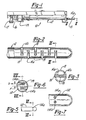
- a sootblower of the long retracting variety is shown and is designated generally by reference character 10, the general construction of which is disclosed by US-A-3 439 376 granted to J. W. Nelson et al on April 22, 1969. Numerous additional features have been incorporated into sootblowers of the type shown subsequent to the above-mentioned disclosure; however, such details are not involved in the present invention.
- the sootblower depicted by Fig. 1 will be recognized as typical of the structural environment wherein the present invention can be advantageously employed.
- Figure 1 illustrates the novel means of employing a plurality of nozzles at various positions according to the first embodiment of this invention, which is further shown by Figures 2, 3 and 4.
- Lance tube 12 shown in Figure 1, is inserted reciprocally into a boiler or furnace presumed to be located to the right in the illustration to clean the heat exchanging and other interior surfaces by the discharge of blowing agents such as air, water and/or steam from nozzles 14a and 14b.
- Lance tube 12 is affixed to motor driven carriage 15 which controls the movement of the lance tube.
- Carriage 15 imparts a simultaneous rotational and longitudinal motion to lance tube 12 as it is cycled into and withdrawn from the boiler to perform its cleaning function.
- the longitudinal distance over which the lance 12 must move while a complete revolution is achieved is referred to as the helix distance or pitch.
- Lance tube 12 is slidably overfitted upon stationary feed tube 16. Blowing medium supplied to feed tube 16 is controlled by blow valve 17 and is conducted into lance tube 12 and thereafter exists through nozzles 14a and 14b.
- the improved nozzle block indicated by reference character 13 is shown particularly with reference to Figure 2.
- a plurality of nozzles 14a and 14b are shown each having a discharge end 18 fixedly mounted in and discharging through the wall portion of lance tube 12.
- a plurality of nozzles 14a and 14b are located at longitudinally spaced positions along the lance. By placing the nozzles longitudinally apart, a less restricted fluid flow path into each is provided. The greater number of nozzles provides adequate lance cooling flow with nozzles of lesser diameter. Longer nozzle lengths coupled with a smaller throat dimension possible through increasing the total number of nozzles results in production of a more penetrating jet stream discharge for more efficient cleaning performance.
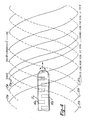
- FIG. 4 The helical paths outlined by nozzles 14a - which are shown initially directed upwardly are designated by reference character 21a, whereas those paths outlined by nozzles 14b, which are initially downwardly directed, are designated by reference character 21b.
- paths 21 a and 21 b form intertwined advancing helical bands.
- Path spacing is chosen such that the jets impact close enough to effectively perform the boiler cleaning functions. Nozzle placement, as described, results in a reduction in lance revolutions necessary to achieve a desired path spacing. It is necessary, however, to choose nozzle longitudinal spacing consistent with the helix distance. In the embodiment illustrated by
- Figure 4 the distance between the furthest separated nozzles is approximately one-half the helix distance.
- a lance tube having nozzles mounted as shown by Figure 2 does, however, result in some non-uniformity in jet path spacing. From Figure 2 it is shown that dimensions A, B, and C, which indicate the distance between adjacent jet paths, are non-uniform since pairs of nozzles are not mounted opposite one another, in which case spacing could be made uniform.
- the advantages of staggered or opposing nozzles are weighed and the appropriate configuration utilized. It is also possible to combine staggered radial and longitudinal nozzle spacing to minimize path irregularities.
- the sootblower lance according to the first embodiment of this invention therefore, produces significant benefits in two areas.
- the second embodiment of the present invention is depicted by Figures 5, 6, and 7 wherein nozzles 114a and 114b are offset from each other in such a manner that their longitudinal axes do not intersect the lance centerline axis. As shown, the nozzles are equidistant from and parallel to a longitudinal diametric center plane of the lance.
- This offset nozzle configuration also permits the installation of longer nozzles than is possible using conventionally directed colinear opposing nozzles. In addition to allowing relatively longer nozzles, this configuration provides a relatively unobstructed nozzle inlet 119 thereby further enhancing compactness of the jet pattern and to increase impact pressure.
- the nozzles are completely offset from each other, and that this permits each nozzle to extend more than halfway across the interior of the lance, as distinguished from prior art arrangements wherein the length of the nozzles must be less than half the internal diameter of the lance tube.
- reaction thrust couple which causes a torque to be applied to the lance.
- the magnitude of the reaction thrust is the mass flow rate through the nozzle times the fluid velocity passing therethrough, or expressed in another way, the reaction thrust is equal to the fluid pressure in the nozzle times a cross-sectional area of the nozzle.
- the reaction force times the length of a line perpendicular to the line of action of a nozzle reaction thrust, measured from the line of action to the center of rotation of lance 112 equals the torque applied to the lance from each nozzle.
- this torque on lance 112 partially offsets the carriage gear force tending to cause lance extension caused by the pressure of blowing medium within the lance.
- the nozzles are offset in a direction such that the jet reaction on the lance opposes its rotation in the direction corresponding to projecting movement.
- the separate embodiments described herein relating to this invention can be combined so that the advantages of both are realized in one structure.
- the nozzles of the lance tube illustrated in Figures 2 and 3 can be offset similarly to the nozzles in Figure 5.
- the nozzles are mounted so that the reaction thrust produced by each acts in the same (retracting) rotational direction so that the force offsetting and retracting assisting features of the second embodiment result.
Claims (5)
Priority Applications (1)
| Application Number | Priority Date | Filing Date | Title |
|---|---|---|---|
| AT85301537T ATE34221T1 (de) | 1984-03-16 | 1985-03-06 | Duesenartiger apparat zur russreinigung. |
Applications Claiming Priority (2)
| Application Number | Priority Date | Filing Date | Title |
|---|---|---|---|
| US06/590,264 US4567622A (en) | 1984-03-16 | 1984-03-16 | Sootblower nozzle apparatus |
| US590264 | 1996-01-23 |
Publications (2)
| Publication Number | Publication Date |
|---|---|
| EP0159128A1 EP0159128A1 (de) | 1985-10-23 |
| EP0159128B1 true EP0159128B1 (de) | 1988-05-11 |
Family
ID=24361539
Family Applications (1)
| Application Number | Title | Priority Date | Filing Date |
|---|---|---|---|
| EP85301537A Expired EP0159128B1 (de) | 1984-03-16 | 1985-03-06 | Düsenartiger Apparat zur Russreinigung |
Country Status (14)
| Country | Link |
|---|---|
| US (1) | US4567622A (de) |
| EP (1) | EP0159128B1 (de) |
| JP (1) | JPS60259815A (de) |
| KR (1) | KR850007675A (de) |
| AT (1) | ATE34221T1 (de) |
| AU (1) | AU565217B2 (de) |
| BR (1) | BR8501155A (de) |
| CA (1) | CA1259003A (de) |
| DE (1) | DE3562670D1 (de) |
| ES (1) | ES541300A0 (de) |
| FI (1) | FI80519C (de) |
| IN (1) | IN161630B (de) |
| MX (1) | MX162360A (de) |
| ZA (1) | ZA851338B (de) |
Families Citing this family (20)
| Publication number | Priority date | Publication date | Assignee | Title |
|---|---|---|---|---|
| US5241723A (en) * | 1991-10-21 | 1993-09-07 | The Babcock & Wilcox Company | Nozzle structure with improved stream coherence |
| WO1993014887A1 (en) * | 1992-01-23 | 1993-08-05 | Institut Teplofiziki Sibirskogo Otdelenia Akademii Nauk Sssr | Method and device for removing ash deposits from the surfaces of technological installations |
| US5271356A (en) * | 1992-10-01 | 1993-12-21 | The Babcock And Wilcox Company | Low profile sootblower nozzle |
| US5375771A (en) * | 1993-02-10 | 1994-12-27 | Jameel; Mohomed I. | Advanced sootblower nozzle design |
| US5355844A (en) * | 1993-05-26 | 1994-10-18 | Kendrick William E | System for slag removal and the like |
| US5423483A (en) * | 1993-11-12 | 1995-06-13 | Schwade; Hans H. | Sootblower |
| US6764030B2 (en) | 2001-01-12 | 2004-07-20 | Diamond Power International, Inc. | Sootblower nozzle assembly with an improved downstream nozzle |
| US7028926B2 (en) * | 2001-01-12 | 2006-04-18 | Diamond Power International, Inc. | Sootblower nozzle assembly with nozzles having different geometries |
| DE102004049797A1 (de) * | 2004-10-12 | 2006-04-13 | Kipp, Jens-Werner | Verfahren und Vorrichtung zur Geräuschreduzierung von Strahldüsen |
| US20070045584A1 (en) * | 2005-08-31 | 2007-03-01 | Diamond Power International, Inc. | Low loss poppet valve for a cleaning device and a method of delivering a cleaning fluid therewith |
| US8381690B2 (en) | 2007-12-17 | 2013-02-26 | International Paper Company | Controlling cooling flow in a sootblower based on lance tube temperature |
| US7865996B1 (en) | 2009-12-18 | 2011-01-11 | Diamond Power International, Inc. | Sootblower with progressive cleaning arc |
| FR3008452B1 (fr) * | 2013-07-10 | 2015-07-24 | Claude Favy | Dispositif permettant la detente diphasique d'un important debit saturant |
| US9541282B2 (en) | 2014-03-10 | 2017-01-10 | International Paper Company | Boiler system controlling fuel to a furnace based on temperature of a structure in a superheater section |
| JP6463831B2 (ja) | 2014-07-25 | 2019-02-06 | インターナショナル・ペーパー・カンパニー | ボイラ伝熱面上のファウリングの場所を判定するためのシステムおよび方法 |
| US9927231B2 (en) * | 2014-07-25 | 2018-03-27 | Integrated Test & Measurement (ITM), LLC | System and methods for detecting, monitoring, and removing deposits on boiler heat exchanger surfaces using vibrational analysis |
| KR101748802B1 (ko) * | 2016-10-18 | 2017-06-19 | 주식회사 지스코 | 수트 블로워 및 이를 이용한 튜브형 열 교환기의 세정 방법 |
| CN108662599B (zh) * | 2018-05-23 | 2023-10-20 | 浙江浙能技术研究院有限公司 | 一种带蒸汽射流辅助的吹灰器和吹灰器的使用方法 |
| IT201800010480A1 (it) * | 2018-11-21 | 2020-05-21 | Francesco Autelli | Apparecchiatura per la rimozione dei residui di combustione |
| DE102021130293A1 (de) | 2021-11-19 | 2023-05-25 | Clyde Bergemann Gmbh Maschinen- Und Apparatebau | Rußbläser, industrielle Verbrennungsanlage und Verwendung eines Rußbläsers |
Family Cites Families (21)
| Publication number | Priority date | Publication date | Assignee | Title |
|---|---|---|---|---|
| US2897532A (en) * | 1959-08-04 | Retractable soot blower of the long travel type | ||
| US1902736A (en) * | 1922-11-06 | 1933-03-21 | Diamond Power Speciality | Boiler cleaner |
| US1944325A (en) * | 1924-09-22 | 1934-01-23 | Diamond Power Speciality | Boiler cleaner |
| US1785821A (en) * | 1925-06-29 | 1930-12-23 | Diamond Power Speciality | Boiler cleaner |
| US2023108A (en) * | 1931-04-27 | 1935-12-03 | Diamond Power Speciality | Boiler cleaner |
| US1966912A (en) * | 1931-06-22 | 1934-07-17 | Diamond Power Speciality | Boiler tube cleaning construction |
| US2441112A (en) * | 1944-06-09 | 1948-05-04 | Vulcan Soot Blower Corp | Retractable soot blower |
| NL113419C (de) * | 1958-05-14 | 1900-01-01 | ||
| US3138819A (en) * | 1960-02-09 | 1964-06-30 | Babcock & Wilcox Ltd | Fluid heater cleaners |
| US3216044A (en) * | 1962-10-22 | 1965-11-09 | Diamond Power Speciality | Long travel soot blower with contoured rail |
| US3216045A (en) * | 1964-04-22 | 1965-11-09 | Diamond Power Speciality | Lance tube deflection compensator for long retracting blower |
| US3439376A (en) * | 1965-09-09 | 1969-04-22 | Diamond Power Speciality | Long retracting soot blower |
| US3436786A (en) * | 1966-12-28 | 1969-04-08 | Combustion Eng | Retractable soot blower organization |
| JPS4817501B1 (de) * | 1970-02-20 | 1973-05-30 | ||
| JPS4817501U (de) * | 1971-07-12 | 1973-02-27 | ||
| DD137814A3 (de) * | 1976-05-20 | 1979-09-26 | Bernd Weiser | Kurzrohr-russblaeser |
| US4173808A (en) * | 1979-01-05 | 1979-11-13 | Combustion Engineering, Inc. | Soot blower for tube bundle in pressurized enclosure |
| US4209028A (en) * | 1979-05-29 | 1980-06-24 | Babcock & Wilcox Company | Lance construction for boiler cleaning apparatus |
| US4407237A (en) * | 1981-02-18 | 1983-10-04 | Applied Engineering Co., Inc. | Economizer with soot blower |
| US4346674A (en) * | 1981-02-18 | 1982-08-31 | Applied Engineering, Inc. | Economizer with soot blower |
| CA1172244A (en) * | 1981-12-29 | 1984-08-07 | Charles W. Hammond | Method and apparatus for removing deposits from highly heated surfaces |
-
1984
- 1984-03-16 US US06/590,264 patent/US4567622A/en not_active Expired - Lifetime
-
1985
- 1985-02-21 ZA ZA851338A patent/ZA851338B/xx unknown
- 1985-02-21 CA CA000474858A patent/CA1259003A/en not_active Expired
- 1985-03-01 IN IN156/CAL/85A patent/IN161630B/en unknown
- 1985-03-06 AT AT85301537T patent/ATE34221T1/de not_active IP Right Cessation
- 1985-03-06 EP EP85301537A patent/EP0159128B1/de not_active Expired
- 1985-03-06 DE DE8585301537T patent/DE3562670D1/de not_active Expired
- 1985-03-07 AU AU39626/85A patent/AU565217B2/en not_active Ceased
- 1985-03-14 MX MX204620A patent/MX162360A/es unknown
- 1985-03-14 FI FI851020A patent/FI80519C/fi not_active IP Right Cessation
- 1985-03-15 BR BR8501155A patent/BR8501155A/pt unknown
- 1985-03-15 KR KR1019850001671A patent/KR850007675A/ko not_active Application Discontinuation
- 1985-03-15 ES ES541300A patent/ES541300A0/es active Granted
- 1985-03-16 JP JP60053209A patent/JPS60259815A/ja active Granted
Also Published As
| Publication number | Publication date |
|---|---|
| KR850007675A (ko) | 1985-12-07 |
| FI851020L (fi) | 1985-09-17 |
| JPS60259815A (ja) | 1985-12-21 |
| DE3562670D1 (de) | 1988-06-16 |
| ATE34221T1 (de) | 1988-05-15 |
| FI80519B (fi) | 1990-02-28 |
| CA1259003A (en) | 1989-09-05 |
| ES8603640A1 (es) | 1985-12-16 |
| AU3962685A (en) | 1985-09-19 |
| JPH049967B2 (de) | 1992-02-21 |
| FI80519C (fi) | 1990-06-11 |
| US4567622A (en) | 1986-02-04 |
| IN161630B (de) | 1988-01-02 |
| ES541300A0 (es) | 1985-12-16 |
| BR8501155A (pt) | 1985-11-12 |
| EP0159128A1 (de) | 1985-10-23 |
| MX162360A (es) | 1991-04-26 |
| AU565217B2 (en) | 1987-09-10 |
| FI851020A0 (fi) | 1985-03-14 |
| ZA851338B (en) | 1985-10-30 |
Similar Documents
| Publication | Publication Date | Title |
|---|---|---|
| EP0159128B1 (de) | Düsenartiger Apparat zur Russreinigung | |
| US5337438A (en) | Method and apparatus for constant progression of a cleaning jet across heated surfaces | |
| US4492187A (en) | Sootblower apparatus | |
| US5379727A (en) | Low profile sootblower nozzle | |
| CA2366806C (en) | Sootblower nozzle assembly with an improved downstream nozzle | |
| US6575122B2 (en) | Oscillating sootblower mechanism | |
| US5241723A (en) | Nozzle structure with improved stream coherence | |
| US4359800A (en) | Sootblower feed and lance tube structure with improved turbulizer system | |
| US6772775B2 (en) | Sootblower mechanism providing varying lance rotational speed | |
| RU2052145C1 (ru) | Способ преобразования тепловой энергии в механическую в газотурбинном двигателе и газотурбинный двигатель (варианты) | |
| US7028926B2 (en) | Sootblower nozzle assembly with nozzles having different geometries | |
| CN108686511A (zh) | 一种反应塔清灰装置 | |
| SU870906A1 (ru) | Устройство дл предотвращени образовани накипи | |
| JP2010156522A (ja) | 熱交換器の灰除去方法及びスートブロワ | |
| JP2001021131A (ja) | スーツブロワ | |
| CN114165799A (zh) | 一种滑差式锅炉脉冲吹灰装置 | |
| JPS5838314Y2 (ja) | 熱交換器伝熱面の清浄装置 | |
| JPS5899611A (ja) | 首振噴射ノズル付ス−トブロワ | |
| JPH08121740A (ja) | スートブロワ | |
| MXPA02004771A (es) | Ensamble de toberia sopladora de hollin con una tobera corriente abajo mejorada. | |
| JP2001041684A (ja) | スートブロワ |
Legal Events
| Date | Code | Title | Description |
|---|---|---|---|
| PUAI | Public reference made under article 153(3) epc to a published international application that has entered the european phase |
Free format text: ORIGINAL CODE: 0009012 |
|
| AK | Designated contracting states |
Designated state(s): AT BE CH DE FR GB IT LI LU NL SE |
|
| 17P | Request for examination filed |
Effective date: 19851015 |
|
| 17Q | First examination report despatched |
Effective date: 19860317 |
|
| D17Q | First examination report despatched (deleted) | ||
| GRAA | (expected) grant |
Free format text: ORIGINAL CODE: 0009210 |
|
| AK | Designated contracting states |
Kind code of ref document: B1 Designated state(s): AT BE CH DE FR GB IT LI LU NL SE |
|
| REF | Corresponds to: |
Ref document number: 34221 Country of ref document: AT Date of ref document: 19880515 Kind code of ref document: T |
|
| ITF | It: translation for a ep patent filed |
Owner name: ING. A. GIAMBROCONO & C. S.R.L. |
|
| REF | Corresponds to: |
Ref document number: 3562670 Country of ref document: DE Date of ref document: 19880616 |
|
| ET | Fr: translation filed | ||
| PLBE | No opposition filed within time limit |
Free format text: ORIGINAL CODE: 0009261 |
|
| STAA | Information on the status of an ep patent application or granted ep patent |
Free format text: STATUS: NO OPPOSITION FILED WITHIN TIME LIMIT |
|
| 26N | No opposition filed | ||
| PGFP | Annual fee paid to national office [announced via postgrant information from national office to epo] |
Ref country code: FR Payment date: 19910321 Year of fee payment: 7 |
|
| ITTA | It: last paid annual fee | ||
| PGFP | Annual fee paid to national office [announced via postgrant information from national office to epo] |
Ref country code: LU Payment date: 19910331 Year of fee payment: 7 |
|
| PGFP | Annual fee paid to national office [announced via postgrant information from national office to epo] |
Ref country code: SE Payment date: 19920213 Year of fee payment: 8 |
|
| PGFP | Annual fee paid to national office [announced via postgrant information from national office to epo] |
Ref country code: AT Payment date: 19920214 Year of fee payment: 8 |
|
| PGFP | Annual fee paid to national office [announced via postgrant information from national office to epo] |
Ref country code: CH Payment date: 19920218 Year of fee payment: 8 |
|
| PGFP | Annual fee paid to national office [announced via postgrant information from national office to epo] |
Ref country code: DE Payment date: 19920220 Year of fee payment: 8 |
|
| PGFP | Annual fee paid to national office [announced via postgrant information from national office to epo] |
Ref country code: GB Payment date: 19920227 Year of fee payment: 8 Ref country code: BE Payment date: 19920227 Year of fee payment: 8 |
|
| PG25 | Lapsed in a contracting state [announced via postgrant information from national office to epo] |
Ref country code: LU Free format text: LAPSE BECAUSE OF NON-PAYMENT OF DUE FEES Effective date: 19920306 |
|
| PGFP | Annual fee paid to national office [announced via postgrant information from national office to epo] |
Ref country code: NL Payment date: 19920331 Year of fee payment: 8 |
|
| PG25 | Lapsed in a contracting state [announced via postgrant information from national office to epo] |
Ref country code: FR Effective date: 19921130 |
|
| REG | Reference to a national code |
Ref country code: FR Ref legal event code: ST |
|
| PG25 | Lapsed in a contracting state [announced via postgrant information from national office to epo] |
Ref country code: GB Effective date: 19930306 Ref country code: AT Effective date: 19930306 |
|
| PG25 | Lapsed in a contracting state [announced via postgrant information from national office to epo] |
Ref country code: SE Effective date: 19930307 |
|
| PG25 | Lapsed in a contracting state [announced via postgrant information from national office to epo] |
Ref country code: LI Effective date: 19930331 Ref country code: CH Effective date: 19930331 Ref country code: BE Effective date: 19930331 |
|
| BERE | Be: lapsed |
Owner name: THE BABCOCK & WILCOX CY Effective date: 19930331 |
|
| PG25 | Lapsed in a contracting state [announced via postgrant information from national office to epo] |
Ref country code: NL Effective date: 19931001 |
|
| GBPC | Gb: european patent ceased through non-payment of renewal fee |
Effective date: 19930306 |
|
| NLV4 | Nl: lapsed or anulled due to non-payment of the annual fee | ||
| REG | Reference to a national code |
Ref country code: CH Ref legal event code: PL |
|
| PG25 | Lapsed in a contracting state [announced via postgrant information from national office to epo] |
Ref country code: DE Effective date: 19931201 |
|
| EUG | Se: european patent has lapsed |
Ref document number: 85301537.8 Effective date: 19931008 |