The pitot-static system is usually one of those items appearing on your to-do list when you are at the point of being 90% done with 90% to go—as builders like to joke. As such, it is not one of those items that typically gets a great deal of thought as you approach the end phase of airplane construction. It is, however, pretty important and deserves some care in its assembly. Maintenance is minimal, but again, noteworthy, especially for those who fly IFR. Let’s take a look at what makes these systems tick.
System Basics
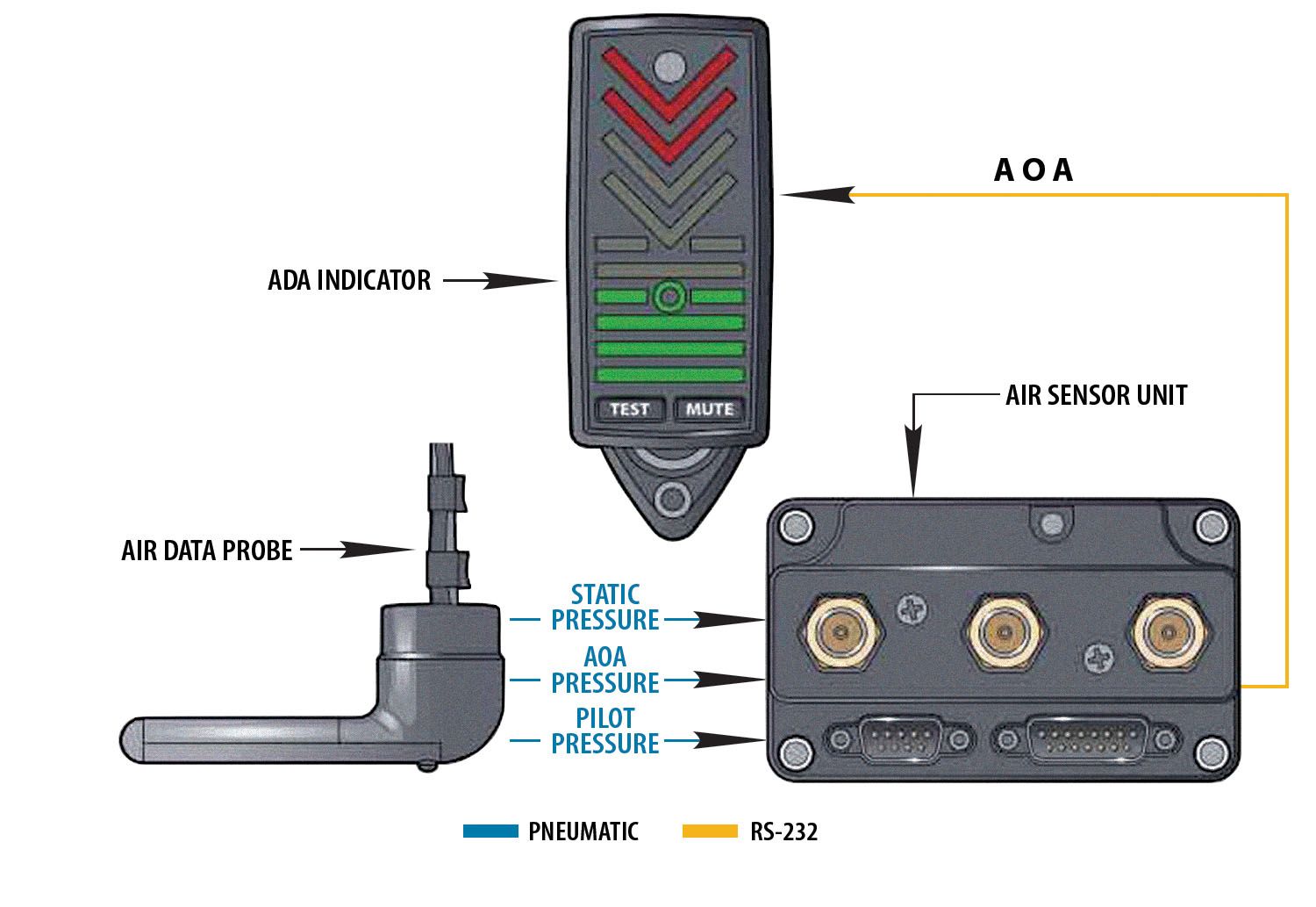
The pitot-static system has two simple jobs: accurately measure the ambient air pressure (static) and accurately measure the air pressure associated with moving the airplane through the atmosphere (pitot). In addition, newer systems are often tasked with measuring differential pressures associated with sensing angle of attack (AOA). We think of this as one system, but it is actually three related systems.
The static system senses ambient pressure needed to work the altimeter, the encoder and the vertical-speed indicator. It also feeds important information to the air-data computer in systems with an AOA indicator such as the popular Garmin G3X. This sounds pretty simple, but the location of the static port is critical because the air pressure on the fuselage varies from one place to another. In most cases, the designer has tested several possible locations and determined the best spot for the static ports. You are free to change the locations if you like, but be aware that you may be compromising the accuracy of the system. It goes without saying that an inaccurate altimeter is a bad thing, especially in instrument conditions.
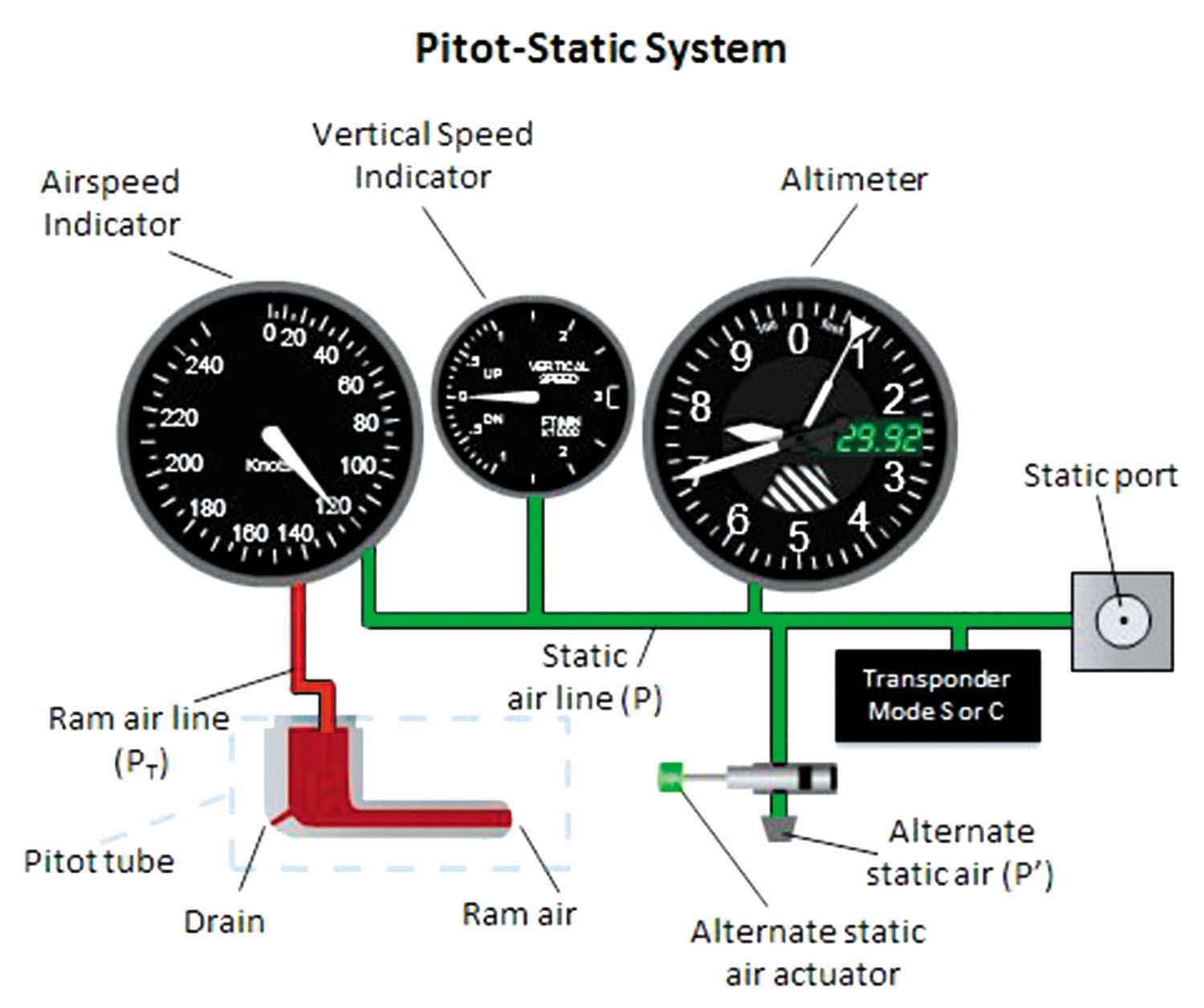
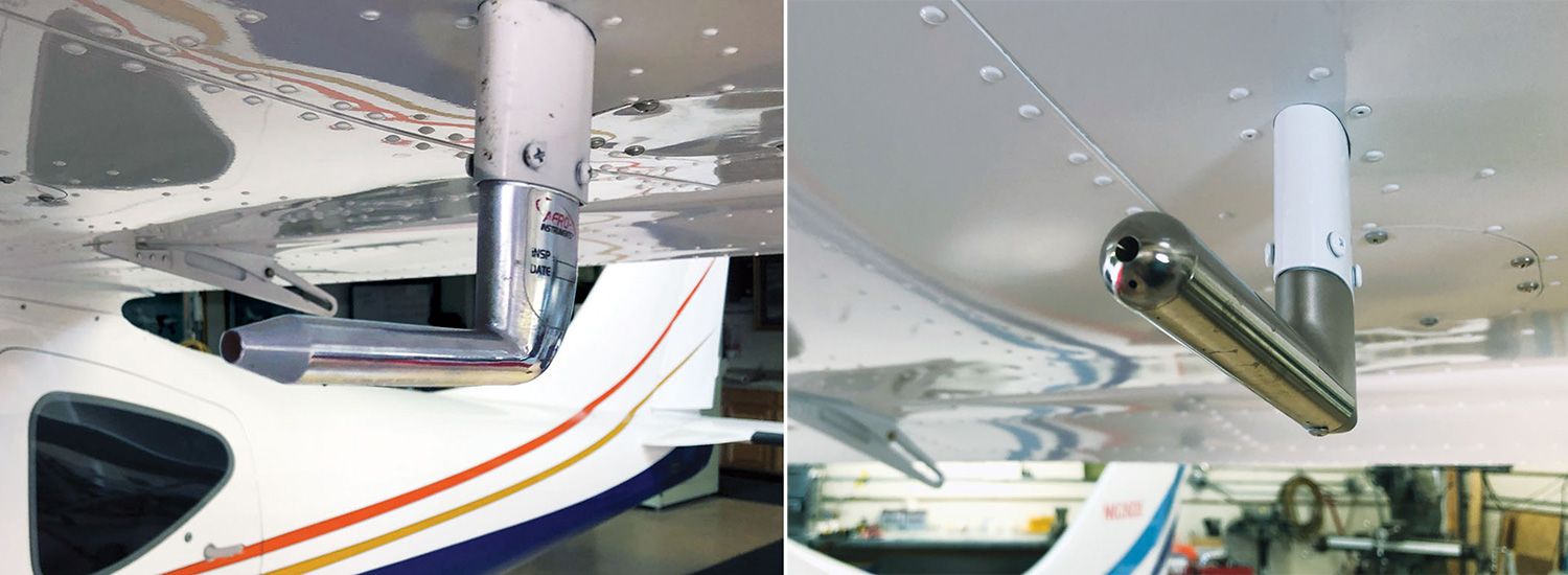
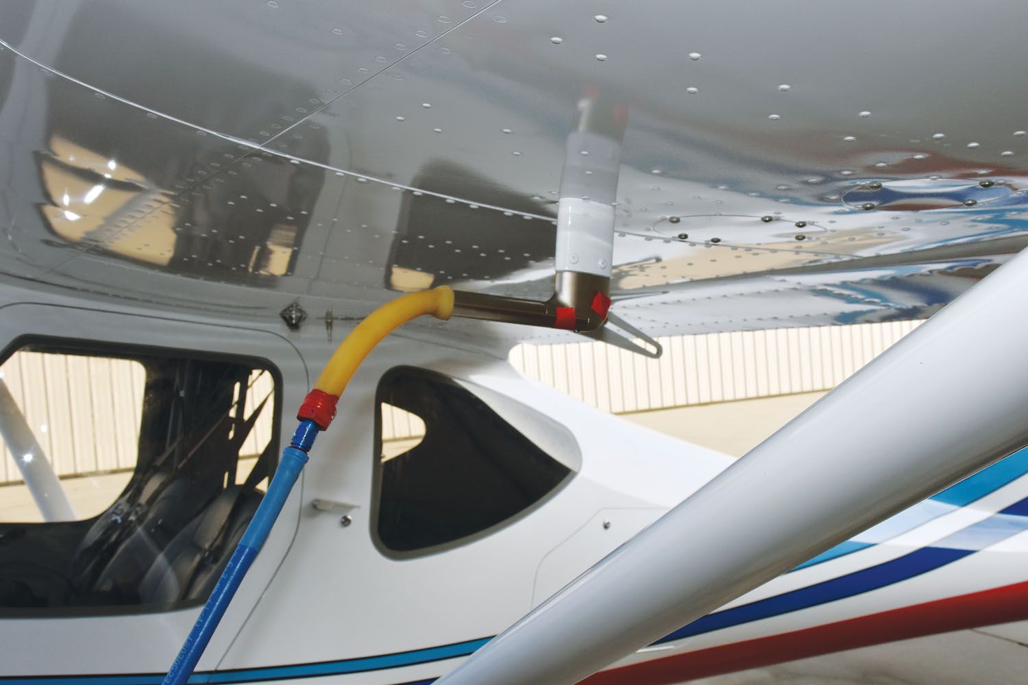
The pitot system senses the pressure caused by the airplane moving through the air, which is vital to the airspeed indicator and the air-data computer if present. The pitot tube, or air-data probe in AOA-equipped systems, is typically located on the underside of the wing near the leading edge, where it has a clear path to the oncoming air. In the case of an air-data probe, there is a second hole angled down at 45° to serve as a reference. Both of these pressure feeds drive the air-data computer.
Aircraft destined for IFR work should have a heated pitot tube or air-data probe. The polarity of the electrical power leads to the pitot heat is important. This seems counterintuitive since the heat is straight resistance heat, but I know this because I had it reversed on my latest project, and the pitot heat wouldn’t work until I fixed it.
Installation
Install the static ports in the locations recommended by your kit manufacturer. If you are building from plans or your own design, you can look at similar planes for location guidance. Just know that you may have to do some additional testing and possibly move your static ports if they are not providing accurate pressures to the affected instruments.
A good rule to remember is that the line from the static port should head uphill from the port if possible. This is to keep water from entering the system—or if it does, to let it drain on its own. In systems with two static ports, lines from both ports should be tied together to present a single line or static reference to the instruments.
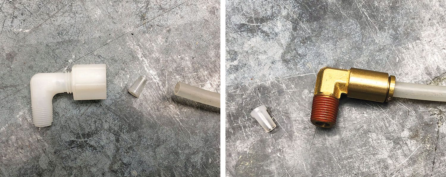
The static system lines are typically 1/4-inch nylon tubing or a similar material. Fittings can be nylon compression fittings or, as many now prefer, push-on fittings. Push-on fittings come in plastic or brass. Nylon fittings are less expensive but take greater care to install. Over-tightening can distort the fitting and lead to leaks. Of course, under-tightening can also cause leaks. That said, I have been using nylon fittings for 20 years and have not had any problems.
Most Experimentals do not include an alternate static source, instead relying on two static ports for redundancy. If you choose to install an alternate static source, it should be activated with a small valve easily accessible to the pilot. Please note that the instruments will read differently when using a cabin-based alternate static source. This is something you should check out during Phase I flight testing.
The pitot tube or air-data probe attaches to the underside of the wing, again in the recommended location in the case of kit projects. For others, look at similar planes for location guidance. The important thing is to avoid locating the pitot tube near landing gear or wing struts where the air might be disturbed by such items. Things like GoPro cameras should be kept well clear of the pitot tube.
Pitot heat will usually need 14- or 16-gauge wire. Check with the manufacturer’s literature for current requirements and refer to AC 43.13-1B, Section 11, for wire size tables.
Be sure to reinforce the area surrounding the pitot tube to prevent bending and cracking of the wing skin under loads.
Pitot and AOA lines will also usually be 1/4-inch OD nylon tubing with either nylon or push-on fittings. Be sure to use different colored lines for the pitot tube and the AOA sensor lines, or at least clearly label them. Once the wing is closed, it can be easy to confuse the two if they are the same color.
When installing pitot-static fittings, be sure to use a suitable thread sealant where you encounter pipe fittings, such as going into the back of instruments. Do not use Teflon tape on these fittings because of the risk of tape shards getting into the instruments. Do not use sealant on AN or compression fittings.
Pitot-Static System Testing
Planes that will never fly IFR do not need to have their pitot-static systems tested. However, it is a really good idea to have the system on a new plane tested at least once. Aircraft that will be flying in Class B, C or D airspace will need to have the transponder checked and certified biennially. The pitot system does not need recurrent checking for VFR-only aircraft. Planes that might end up in the clouds must have both systems tested initially and every two years to remain legal. This is usually done at the same time and by the same person who certifies the transponder.

To perform a static system test, a technician will block off one static port and attach a suction device to the other port. The test will typically simulate various altitudes up to 20,000 feet for most Experimentals. At low altitudes, the accuracy tolerance is only 20–30 feet. At 20,000 feet, the tolerance widens to 130 feet. In between, at 10,000 feet, the tolerance is 80 feet. The altimeter and encoder must be within those tolerances to be certified. If the inaccuracy comes from system leakage, the leak must be tracked down by testing sections of the system until the leak is found and repaired. If the leak is in a device, say an altimeter, it must be repaired, usually by an instrument repair shop.
While performing the static system test, the technician will tap on the panel at some point to see if the altimeter needle moves. At low altitudes, the needle may not move more than 70 feet, and hopefully less. This is to detect friction in the altimeter and is called a friction test. In planes with glass panels, this test is not required. Please refer to 14 CFR 91.411 and 14 CFR 43, appendix E, to get more details on these tests.
With the static system working well, it is time to move to the pitot system. The pitot tube test requires a sealed connection between the test instrument and the pitot tube. This usually requires some sort of adapter. In the case of an air-data probe, it would also require the AOA sensor hole to be blocked off to isolate it from the pitot system. The testing equipment companies are running a little behind on getting the proper adapters made to deal with air-data probes, such as the one Garmin provides with the G3X system. For now, a certain amount of improvisation is required.
With the test equipment connected to the pitot tube, pressure is introduced to simulate various airspeeds to verify the airspeed indicator’s accuracy. These pressures are fairly low. For example, an airspeed of 110 knots requires a pressure of about 0.29 psi. For this reason, it would be a really bad idea to blow shop air into a pitot tube.
The FAA says airspeed (IAS) accuracy must be within 3% of calibrated airspeed or 5 knots, whichever is greater. The speeds must be accurate from 1.3 Vs to Vne.
System Maintenance
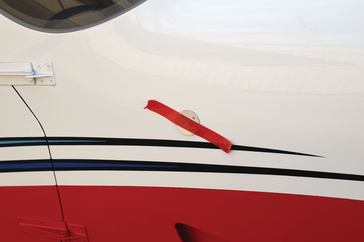
These systems require little maintenance, but it is important to keep the pitot tube clear of insects and debris and to similarly keep the static ports clear. Keeping a cover over the pitot tube is always a good idea, especially if a plane is stored outside. For some reason, wasps seem to like to wedge themselves into pitot tubes. Even in flight, it is possible for a bug to get stuck in the mouth of the tube. Airplane washing provides a great opportunity to get water into the system if some care is not taken. In theory, water will drain out after washing without any special effort, but it is probably safer to keep it out to begin with. Just tape over the pitot and static ports with some high-visibility tape and, of course, remember to remove it before flight.
During your annual condition inspection, you should check pitot and static lines to ensure they are not getting chafed or pinched anywhere. Give fittings a quick check to be sure they are secure. Also check the wing skin around the pitot tube to be sure there are no cracks present. Other than that, there isn’t much in the way of maintenance required for these systems.
Photos: Dave Prizio and courtesy of AVweb.


It is interesting that in the 2nd paragraph of “System Basics”, static pressure is not mentioned for airspeed. It is shown correctly in the illustration, though. Also in that illustration, the standby static source doesn’t cutout the primary static source like it should.
A pitot tube that is toward the wing leading edge (i.e. Cessna) will be adversely affected at higher AOA (low airspeeds at 1G). An under-wing, more aft mounted probe (Piper, Beech, etc.) will be better on airspeed accuracy because it will not see AOA changes as easily.
There are differences in accuracies of the instruments and the values displayed on the instruments in flight versus on the ground.
I am curious as to why not cutting out the primary static source would have any effect on the alternate static source. Piper uses only a petcock valve to ambient in its PA28 series. Just curious.