Description
The PITOBAR Averaging Pitot Tube is used for flow measurement of liquid and gasses in horizontal or vertical pipe lines. The PITOBAR Averaging Pitot Tube principle of operation is derived from the classic or single point pitot tube. As opposed to the single point pitot tube, the PITOBAR averaging pitot tube has a number of holes depending of pipe size pointing towards the up-stream side. One port pointing down stream measures the static pressure. The PITOBAR has very low installation costs and the pressure loss is low compared to other flow elements, especially in larger pipe sizes.
The PITOBAR Averaging Pitot Tube is constructed and designed with a diamond shaped strut with several ports spaced centrally within concentric rings of equal area pointing towards the upstream side. This is done in order to get the best averaging measurement of the dynamic pressure, resulting in a more
accurate flow reading. The pitot tube creates a differential pressure signal which is proportional to the flow rate.
Differential Pressure = ( Pstatic + Pdynamic) – Pstatic.
|
|
|
|
Design and calculation standards
|
VDE/VDI 2640, ASME, DIN, EN 13480
|
|
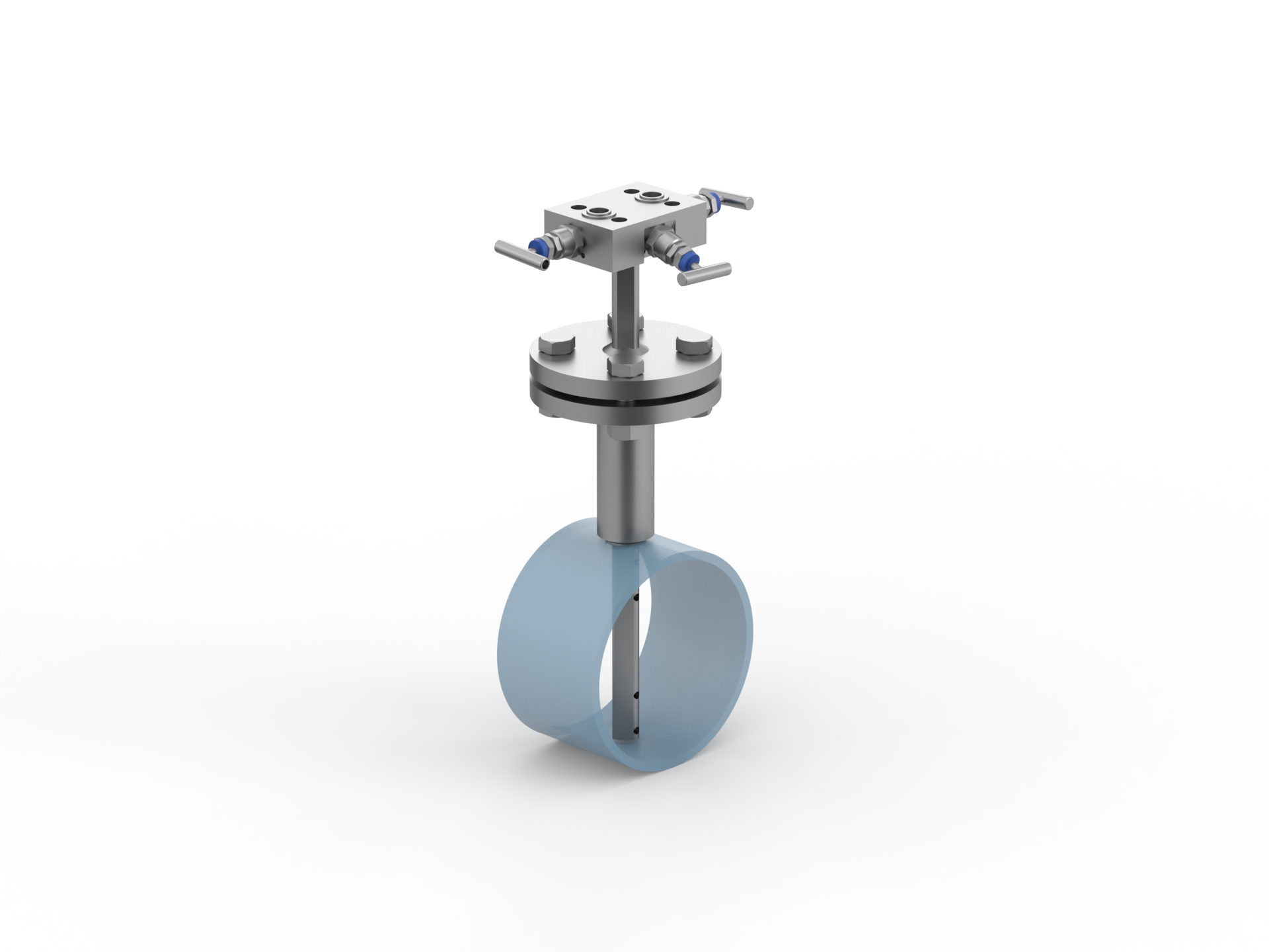
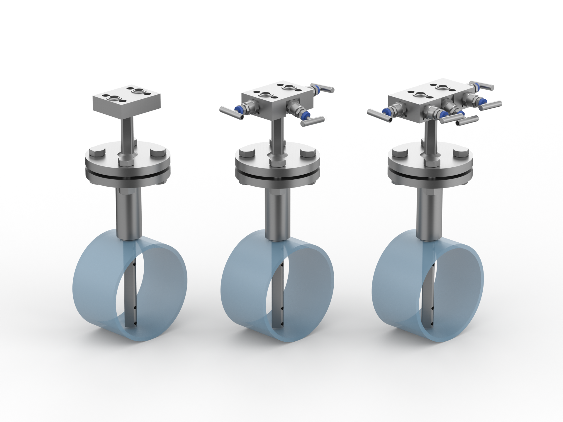
Types
|
DK203 & DK253 with mounting flange. DK204 & DK254 with 3 valve manifold. DK205 & DK255 with 5 valve manifold
|
|
Pipe sizes
|
DK20X: DN80 - DN 1000, 3" - 40" | DK25X: DN80 -DN 2000, 3" - 80"
|
|
Probe sizes
|
DK20X: 20 x 20 mm | DK25X: 25 x 25 mm
|
|
Pressure rating
|
PN 16 - 400, 150 - 2500 lbs, ISO PN 20, 50
|
|
Temperature range
|
-100°C - +350 °C
|
|
Material PITOBAR
|
Stainless steel AISI 316, other stainless grades on request
|
|
Material mounting part
|
Carbon steel, stainless steel AISI 316, other on request
|
|
Process connection
|
Flange according to pressure rating
|
|
Flange standards
|
DIN, ANSI
|
|
Bottom support
|
For larger pipe sizes and high velocities
|
|
Mounting
|
Welding to the pipe
|
|
Instrument connection
|
IEC 61518
|
|
Mounting neck
|
Standard lengths, 130, 180, 250 mm, other lenghts available
|
|
|
|
|
Accuracy
|
± 1% accuracy of actual flow
|
|
Repeatability
|
± 0,1%
|
|
Reynolds no.
|
Minimum 100.000 at full flow
|
|
Rangeability
|
10:1
|
|
Max. fluid velocity
|
liquids 5 m/s, gasses 80 m/s
|
Certain installation requirements for straight pipe lines must be fulfilled in order to achieve the most accurate flow measurement. See table below.
Upstream (x D) |
Downstream (x D) |
|
|---|---|---|
|
Single 90° bend
|
9
|
3
|
|
Two or more 90° bends in the same plane
|
14
|
3
|
|
Two or more 90° bends in in different planes
|
24
|
4
|
Without bottom support, with reference to mechanical bend. Pressure is measured in bar. See table below.
Length |
DK200 @ 20°C |
DK200 @ 400°C |
DK250 @ 20°C |
DK250 @ 400°C |
|---|---|---|---|---|
|
200
|
3,75
|
1,81
|
|
|
|
300
|
1,66
|
0,81
|
2,52
|
1,19
|
|
400
|
0,94
|
0,45
|
1,42
|
0,67
|
|
500
|
0,60
|
0,29
|
0,91
|
0,43
|
|
600
|
0,42
|
0,20
|
0,63
|
0,30
|
|
700
|
0,31
|
0,15
|
0,46
|
0,22
|
|
800
|
0,23
|
0,11
|
0,35
|
0,17
|
|
1000
|
0,15
|
0,07
|
0,23
|
0,11
|
| Cookie | Duration | Description |
|---|---|---|
| cookielawinfo-checkbox-advertisement | 1 year | Set by the GDPR Cookie Consent plugin, this cookie is used to record the user consent for the cookies in the "Advertisement" category . |
| cookielawinfo-checkbox-analytics | 11 months | This cookie is set by GDPR Cookie Consent plugin. The cookie is used to store the user consent for the cookies in the category "Analytics". |
| cookielawinfo-checkbox-functional | 11 months | The cookie is set by GDPR cookie consent to record the user consent for the cookies in the category "Functional". |
| cookielawinfo-checkbox-necessary | 11 months | This cookie is set by GDPR Cookie Consent plugin. The cookies is used to store the user consent for the cookies in the category "Necessary". |
| cookielawinfo-checkbox-others | 11 months | This cookie is set by GDPR Cookie Consent plugin. The cookie is used to store the user consent for the cookies in the category "Other. |
| cookielawinfo-checkbox-performance | 11 months | This cookie is set by GDPR Cookie Consent plugin. The cookie is used to store the user consent for the cookies in the category "Performance". |
| elementor | never | This cookie is used by the website's WordPress theme. It allows the website owner to implement or change the website's content in real-time. |
| viewed_cookie_policy | 11 months | The cookie is set by the GDPR Cookie Consent plugin and is used to store whether or not user has consented to the use of cookies. It does not store any personal data. |
| Cookie | Duration | Description |
|---|---|---|
| _ga | 2 years | The _ga cookie, installed by Google Analytics, calculates visitor, session and campaign data and also keeps track of site usage for the site's analytics report. The cookie stores information anonymously and assigns a randomly generated number to recognize unique visitors. |
| _ga_* | 1 year 1 month 4 days | Google Analytics sets this cookie to store and count page views. |
| _gat_UA-* | 1 minute | Google Analytics sets this cookie for user behaviour tracking. |
| _gat_UA-151202324-1 | 1 minute | A variation of the _gat cookie set by Google Analytics and Google Tag Manager to allow website owners to track visitor behaviour and measure site performance. The pattern element in the name contains the unique identity number of the account or website it relates to. |
| _gid | 1 day | Installed by Google Analytics, _gid cookie stores information on how visitors use a website, while also creating an analytics report of the website's performance. Some of the data that are collected include the number of visitors, their source, and the pages they visit anonymously. |
| CONSENT | 2 years | YouTube sets this cookie via embedded YouTube videos and registers anonymous statistical data. |
| VISITOR_INFO1_LIVE | 5 months 27 days | YouTube sets this cookie to measure bandwidth, determining whether the user gets the new or old player interface. |
| YSC | session | Youtube sets this cookie to track the views of embedded videos on Youtube pages. |
| yt-remote-connected-devices | never | YouTube sets this cookie to store the user's video preferences using embedded YouTube videos. |
| yt-remote-device-id | never | YouTube sets this cookie to store the user's video preferences using embedded YouTube videos. |
| yt.innertube::nextId | never | YouTube sets this cookie to register a unique ID to store data on what videos from YouTube the user has seen. |
| yt.innertube::requests | never | YouTube sets this cookie to register a unique ID to store data on what videos from YouTube the user has seen. |