The basic working principle of electric linear actuators is to convert the rotary motion into the linear motion. This conversion of motion is done with the help of a gearbox and a lead screw. They are three most important parts of electric linear actuators.
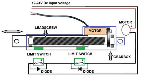
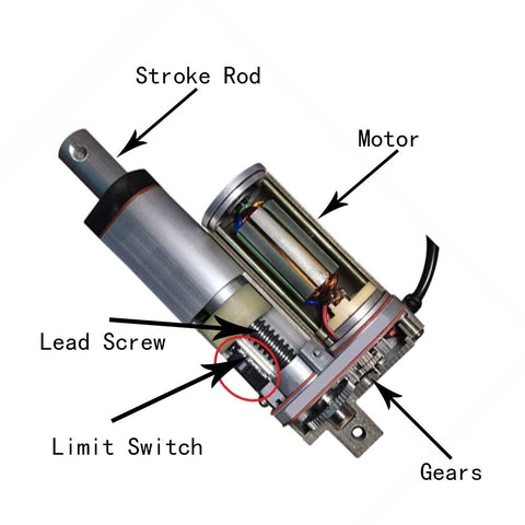
The electric linear actuator is composed of 5 main components: motor, limit switches, lead screw, gears set and stroke rod.
- Motor: This is one of the most important components of linear actuators, which actually provides rotational movement. Usually 12 volt DC or 24 volt DC motors are used, and sometimes AC motors are also used, it interacts with other parts of the linear actuator to achieve linear movement.
- Limit Switch: Each linear actuator has two limit switches. When the stroke rod moves to the extreme position at both ends, the limit switch will be triggered, it will cut off the current of the motor and stop the movement of the stroke rod.
- Lead Screw: The main function of the lead screw is to convert the rotary motion of the motor into the linear motion of the stroke rod. They are installed in the cylinder, the upper part is connected to the stroke rod, the lower part is connected to the gear.
- Gear Set: They act as a connector between the motor and the lead screw, and decelerate the high-speed operation of the motor into the high-torque low-speed rotation of the lead screw.
- Stroke Rod: It is connected to the Lead Screw. When the Lead Screw rotates in the positive direction, the stroke rod moves upward, and when the Lead Screw rotates in the reverse direction, the stroke rod moves downward.
In addition, the electric actuator has an aluminum alloy or polymer plastic shell, which is waterproof and dustproof.
The specific working principle of the electric actuator is as follows:
When the DC motor is connected to the positive DC power supply, the motor rotates in the forward direction and drives the gear to rotate. After the gear set decelerates at high speed, it drives the lead screw to slowly rotate in the forward direction. The lead screw drives the stroke rod to move upward. When the stroke rod moves to the uppermost position, it touches a limit switch, the limit switch cuts off the current of the motor, the motor immediately stops rotating, and the stroke rod stops moving at the same time.
When the DC motor is connected to the reverse DC power supply, the motor rotates in the reverse direction and drives the gear to rotate in the reverse direction, which also drives the screw to rotate in the reverse direction. The lead screw drives the stroke rod to move downward. When the stroke rod moves to the lowest position, it touches another limit switch, the limit switch cuts off the current of the motor, the motor immediately stops rotating, and the stroke rod also stops moving at the same time.