Introduction
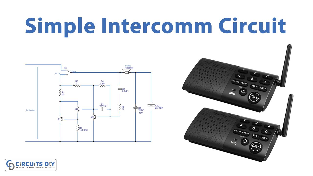
Who hasn’t seen the intercom devices? We all are aware of this electrical two-way communication device. And, if you are an electronics enthusiast, your mind thinks of the making of electronic devices whenever see any. So, for your interest and ease, In this tutorial, we are going to make a “Simple transistor intercom circuit”
An intercom is a standalone voice communications system designed for use within a single building or small group of buildings. It is a two-way communication electronic device with circuits for broadcasting and receiving audio signals.
Hardware Required
| S.no | Component | Value | Qty |
|---|---|---|---|
| 1. | Transistor | – | 3 |
| 2. | Resistor | 2.2M, 150 ohms,1K | 1, 1, 3 |
| 3. | Capacitor | 0.1uf, 0.001uf, 100uf | 1, 1, 1 |
| 4. | Speaker | 8 ohm | 1 |
| 5. | Switch & Battery | – | 1,1 |
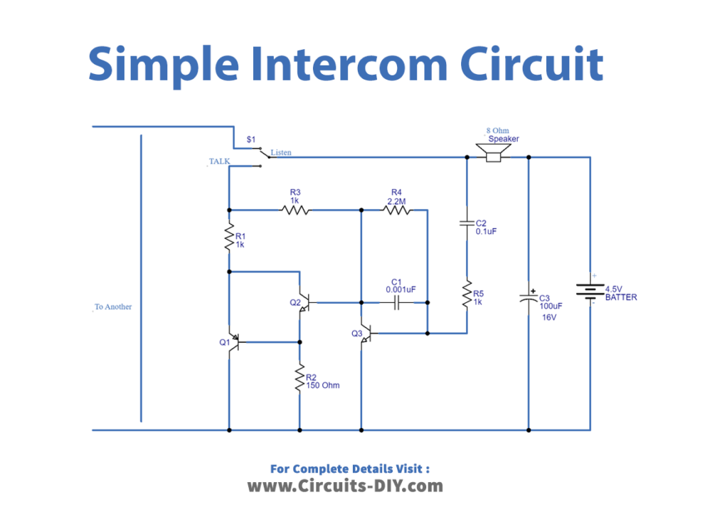
Circuit Diagram
Working Explanation
In this Simple Transistor Intercom circuit, to speak, we first press S1. As a result, the circuit worked as the transmitter. That 8-ohm loudspeaker will serve as a microphone. To communicate with the circuit by sending an audio signal; its coil induces an oscillation, which produces a little signal wave. The 4.5-volt battery is connected, but it does not affect the speaker or the circuit because it is a direct current voltage, which is prevented by a capacitor C2. C2 and resistors R5 receive the AC signal from the speaker. Then, the signal enters Q3’s base. The transistors Q3 and Q2 form a high-gain amplifier circuit. They will then send a signal to drive Q1, which will control the current flowing from the Intercom to another one. And will also pass over the receiver intercom’s speaker (Circuit 2). The sound signal will also be emitted by the speaker. The 4.5-volt battery of the receiving circuit (circuit 2) is a power supply for the transmitter circuit and a speaker that is solely linked via wire.
Application Uses
- Two-way communication circuits.