In this tutorial, we are going to make a ” simple transistor intercom circuit “.
An intercom (intercommunication device), talkback, or door phone is a two-way communication electronic device that contains circuitry to transmit and receive audio transmissions. Imagine your home is large or has a complex structure. And you need to call anyone from another part of your home. But you are busy doing house chores, isn’t it convenient if you can communicate easily with each other through the intercom rather than using cell phone calls? It helped to contact together easily without a walk or shouting until you may have a sore throat or headache.
An intercom is a stand-alone voice communications system. Operating independently of the public telephone network, are generally mounted permanently in buildings and vehicles. Simple intercom circuit using transistors and a few parts. So easy to build and cheaper than ICs. It has less sound. But enough for a quiet home.
Hardware Components
The following components are required to make an Intercom Circuit
| S.no | Component | Value | Qty |
|---|---|---|---|
| 1. | Ceramic Capacitor | 0.001uF, 0.1uF | 1 |
| 2. | Electrolytic Capacitor | 100uF | 1 |
| 3. | Transistor | BD140, BC549 | 1, 1 |
| 4. | Resistor | 0.5W, 0.25W, 1 ohms, 150 ohms, 1K, 2.2M | 2,1, 1, 1, 1, 1 |
| 5. | Switch | – | 1 |
| 6. | Speaker | 8 ohms 0.25 watts | 1 |
| 7. | Battery | 4.5V | 1 |
| 8. | PCB | – | 1 |
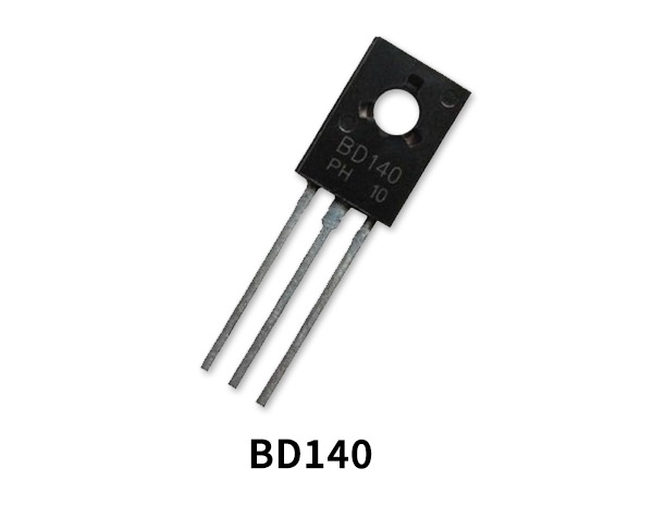
BD140 Pinout
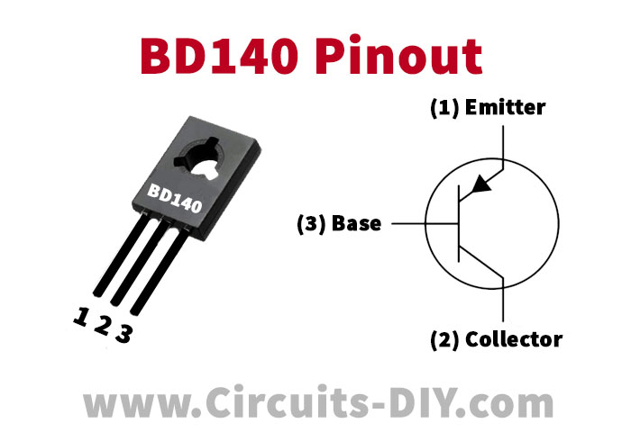
For a detailed description of pinout, dimension features, and specifications download the datasheet of BD140
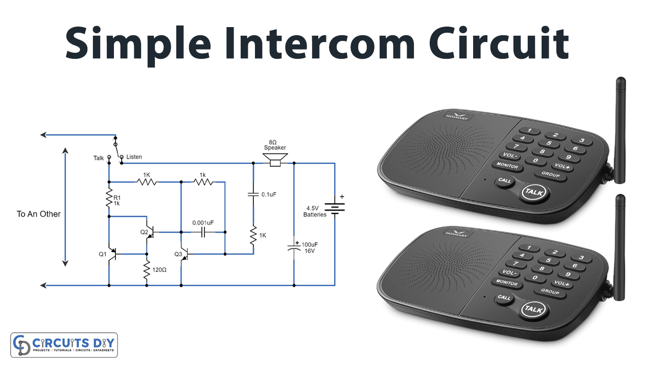
Intercom Circuit
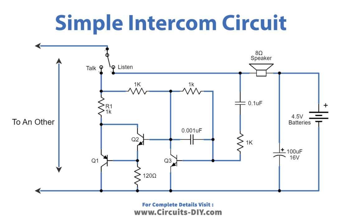
Working Explanation
As shown in the circuit, you can see three transistors and a few other parts that need to complete the circuit.
Press S1 switch to talk. Which allows the circuit to work as the transmitter. When we start speaking into a loudspeaker that will be a microphone. Its inside coils cause an oscillation to generate a tiny signal wave that comes out. These AC signal from the speaker comes to the C2 capacitor and resistors-R5. Then, enter the base of the Q3 transistor. Both NPN transistors Q3 and Q2 act as a high gain amplifier circuit.
Next, they will send a signal to drive PNP transistor Q1, to control the current that flows from the Intercom to another one. Finally, will flow through the speaker of the receiver intercom circuit. Which will also emit the sound signal. The connected 4.5-volt battery does not affect anything with the speaker or the circuit. Because it has DC voltage, the DC volts will be blocked by capacitors-C2. The battery of the receiver circuit is a power supply of a transmitter circuit and a speaker that is connected to wires only.
The work will alternate b/w circuits placed at different parts of the house. When one circuit operates as a transmitter another one operates as a receiver.
The frequency operation of this circuit is based on the sound spoken by humans, Which is range from b/w 200 Hz up to 3 kHz.
Applications
It can be used in small and quiet enough buildings.