Introduction
Intercoms have become an essential communication tool in many households and businesses. A basic intercom circuit allows communication between two or more stations.
This article will discuss the most straightforward form of an intercom circuit, which consists of a microphone, an amplifier, and a speaker. We will also look at the circuit design and how it works.
Hardware Required
| S no | Components | Value | Qty |
|---|---|---|---|
| 1 | Switch | – | 4 |
| 2 | Polar Capacitor | 5, 25, 100uF | 1, 2 |
| 3 | Resistor | 10k, 820k, 82 | 8, 4 |
| 4 | Speaker | – | 1 |
| 5 | Transistor | BC109, AC128 | 2, 1 |
| 6 | Battery | +9v | 2 |
Circuit Diagram
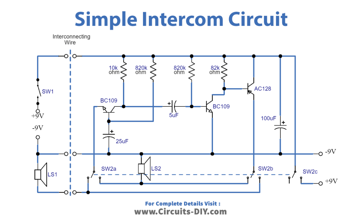
The amplifier and one of the speakers are situated at the master station. At the remote station, often known as the “slave station,” only a speaker and a second battery are present. Since we are using two speakers with low impedance, we must design a special amplifier with low input and output impedance. Also, one contact of each of the speakers should be common to the negative line for different reasons.
Working Explanation
When in the standby position, with neither station making a call, SW1 in the slave unit is open. When the slave wishes to call the master, they close SW1, which applies voltage to the amplifier via one of the interconnecting wires. In the master unit, on standby, SW2 is in the position shown, so the slave’s loudspeaker is connected to the emitter of Tr1.
Tr1 is connected in the standard base mode, and the typical input impedance of a transistor so connected is low, about 50 ohms typical. This impedance closely matches the speaker’s impedance, which should be between 35 and 80 ohms. These impedances are quite common in small speakers. We could use large speakers, and they are generally more efficient, but this will make construction difficult.
The output of the first stage is coupled via C2 to a further stage of amplification, Tr2, which is connected in the common emitter mode. The collector load of this transistor is quite low and must also be accurately chosen. This stage connects to Tr2, which is an inverted PNP transistor. The collector of this goes via the switch to the local speaker, and in this way, the speech at the remote end is heard without any local switching being done.
When the master wishes to call the slave unit, switch SW2 is made. This firstly applies the local battery to the amplifier by SW2c. Secondly, the output of the third transistor is switched to the remote loudspeaker, and thirdly, the local speaker is applied to the input of the amplifier. The same operation occurs, but this time the speech locally originated is heard in the remote loudspeaker.
Current Consumption
The current consumption of the simple intercom circuit is quite high, but this does not matter because an intercom is not likely to be used continually. Both of the switches should be spring-loaded so that while talking, the switch has to be held on; when the conversation has finished, the switch is released, and the unit is turned off.
Value of R4 and B2
The value of R4 in the intercom circuit is critical as it controls the bias in the third stage. The quiescent current must be set to the right level. If it is too low, severe distortion can occur. If it is too high, the transistor may draw very high currents, quickly running down the batteries or even damaging the transistor. Therefore, it is recommended to use the lowest compatible value with acceptable speech quality, and if necessary, a variable resistor can be used in its place.
Similarly, the value of B2 ohms is also essential, and its actual value should be found through experimentation. It should be the lowest possible value that provides acceptable speech quality but should not exceed 20mA if measured on a meter.
Final Words
In conclusion, intercom circuits have come a long way from the simple microphone-amplifier-speaker system to the more sophisticated systems we see today. However, the simple intercom circuit we have discussed here still has a place in many applications where simplicity and economy are important.
By using just one amplifier and two speakers, this circuit design can provide an effective means of communication between two points. The use of low input and low output impedance amplifiers, along with the common negative line for each of the speakers, allows for more efficient use of the circuit and higher-quality audio output.
While there are some technical considerations to keep in mind, such as the values of R4 and B2, these can be determined through experimentation and adjustment to ensure optimal performance. With the use of spring-loaded switches and a heat sink for Tr3, this circuit can provide reliable and safe communication for its users.
We hope you found this article informative and helpful in understanding the basics of a simple intercom circuit. Whether you are looking to build your own intercom or simply interested in the principles behind it, this circuit design is a great starting point.